






This article demonstrates how to accurately measure the speed of light using readily available equipment and the Moku:Lab. Learn the underlying physics and experimental techniques with this comprehensive coursework.
Aims
To measure the speed of light.Learning outcomes
- Improved ability to identify limitations of an experiment in producing accurate and precise results
- Improved ability to use an oscilloscope.
- Familiarity with a phasemeter and how it works.
- Familiarity and competence with laser safety and optical equipment.
Motivation
Preliminary exercises
2. Figure 1 shows the setup of an experiment to measure the speed of light. A laser is pulsed onto a reflector, and the time for the pulse to return back to the laser is measured using a co-located detector with some inherent system time delay tsys. The reflector is positioned first at a distance 1.5m from the detector, and a time of flight t1= 2.53 ns measured. The reflector is then moved to 1.75 m from the detector, and a time of flight t2= 4.19 ns measured. From these time measurements, calculate the speed of light:
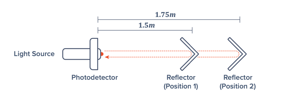
Figure 1: Simple time flight experiment measuring the speed of light
3. Figure 2 shows the setup of an experiment to measure the speed of light. A laser is configured to output a beam of light with 10 MHz sinusoidal amplitude, and directed towards a reflector. A photodetector is co-located on the laser, and enables measurement of the phase of the reflected beam of light. The reflector is initially positioned at 1 m from the laser, and the phase of the reflected beam measured as φ1 = (0.35 * 2π) rad. The reflector is then moved to a distance 2.5 m from the detector and the phase of the reflected beam measured to be φ2 = (0.45 * 2π) rad. From these phase measurements, calculate the speed of light: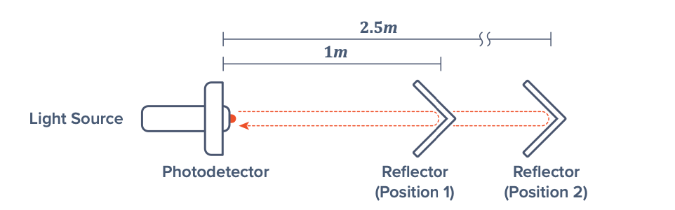
Figure 2: Simple phase measurement experiment measuring the speed of light
Phase 1: Time of flight method
Background

Figure 3: Light will take a finite amount of time, t, to travel over a distance of d
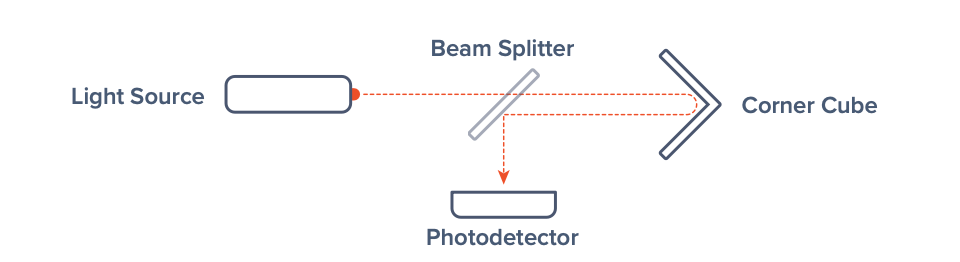
Figure 4: Addition of a photo detector to the simplified time of flight setup


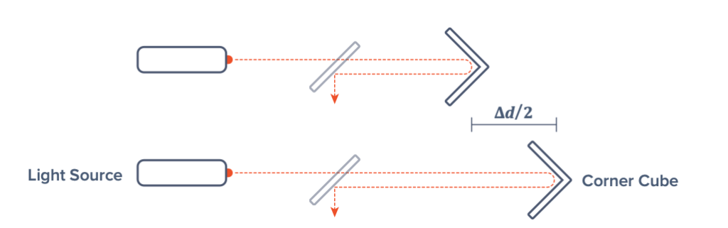
Figure 5: Reflector displacement causes a propagation time delay
- Moku:Lab device
- iPad
- High-speed photo detector
- Power supply
- Beam splitter
- Focusing lens
- Corner cube reflector
- Laser
- Meter ruler
- Optical rails
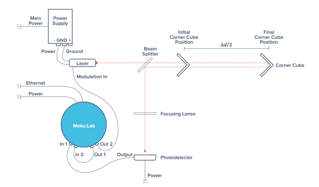
Figure 6: Speed of light experiment setup
Method
- Set up the equipment as in Figure 6, ensuring the power supply and Moku:Lab outputs are switched OFF. Note that the corner cube reflector is connected to the 1-meter optical rail.
- On the iPad, connect to the Moku:Lab Oscilloscope instrument (see Appendix if you are unsure of how to do this).
- On the Oscilloscope, select Input 1 and Input 2 waveforms to be viewable.
- Turn the photo detector ON using the top switch to position “|.”
- Confirm the laser is directed on the desired optical path (as shown in Figure 6).
- Ensure the power supply is turned to 0 V and 0 A before switching it ON, and then increase voltage to just above 5 V with a small amount of current to activate the laser.
- Use the Oscilloscope synthesizer to generate a 500 mVpp 30 MHz square wave on both Output 1 and Output 2 to act as a reference signal and laser amplitude control signal, respectively. Ensure the outputs are switched ON.
- Set the Oscilloscope to trigger on the rising edge of reference signal Input 2. Scale the Input 2 waveform so you can view a few square wave cycles, and adjust the trigger level as required.
- Align the laser and optical elements so the light hits the centre of the photo detector. As the corner cube will be moved throughout the experiment, it should remain aligned when slid along the entire 1-meter rail. (Hint: When aligned, the photo detector signal on Input 1 should resemble the pulsing control signal which is being viewed on Input 2 (a square wave). It is easier to align the corner cube at each end of the 1-meter rail independently. To achieve the best alignment, observe and maximize the amplitude of the photo detector signal while adjusting the optical equipment.)
- Position the corner cube so it is at one end of the optical rail (i.e., close to the beam splitter).
- On the Oscilloscope, use cursors to measure and record the time between the laser control signal rising edge (Input 2), and the rising edge of the detected beam (Input 1). Note: t = 0 should already correspond to a rising edge of Input 2 if you are triggering correctly.
- Move the corner cube to multiple different positions along the rail, noting the displacement from the initial corner cube position in Step 10. With each new position, record the time of flight as in Step 11.
- Using the equations presented in the background section, and the time of flight measurements taken at varying corner cube positions, use a line of best fit method to calculate the speed of light, c.
Questions
- How does the calculated speed of light compare to the accepted value of 299 792 458 m/s?
- What are the primary sources of error in this experiment?
- How could the accuracy be improved?
- How could the precision be improved?
Phase 2: Phase measurement method
Background
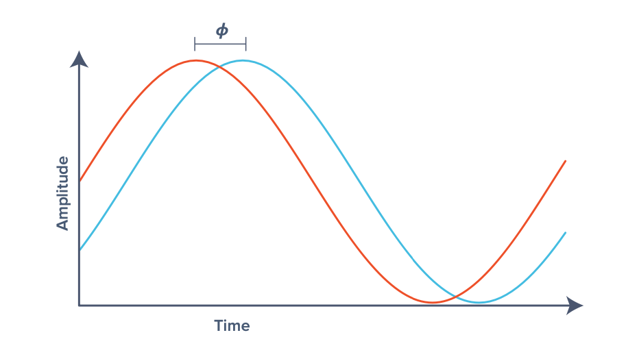
Figure 7: Sine wave phase change due to changing propagation distance



Equipment
Safety
Setup
Method
- If not already done so, set up the equipment as in Figure 4 and follow steps 1-9 of “Phase 1: Time of flight method” section method to configure the equipment and align the optics.
- Open the Moku:Lab Phasemeter instrument (see Appendix if you are unsure of how to do this).
- Configure the Phasemeter to generate a 500 mVpp, 30 MHz sine wave on Output 1 and Output 2. Ensure the outputs are switched ON.
- Configure the locking frequency of both input channels to be 30 MHz.
- Position the corner cube to be at one end of the optical rail (i.e., close to the beam splitter).
- Switch to “Phase” measurement of the Phasemeter, and ensure measurements are in units of radians.
- Press “reacquire” to reset the locking loop and obtain the initial phase offset measurement. Note the Δφ value.
- Slowly slide the corner cube to multiple positions along the rail, ensuring you measure the displacement of each new position with respect to the initial position from Step 5. Record the Δφ value at each new position.
- You should observe the linear change in phase Δφ as you slide the corner cube along the rail. Note: To avoid losing phase lock, it is important that the laser beam is not interfered with during this process. Any movement of the corner cube between positions should be slow and continuous.
- Using each of the phase and displacement measurements, and the equations provided in the background section, use a line of best fit (or similar) method to calculate the speed of light.
Questions
- How does the calculated value compare with the accepted figure of 299 792 458 m/s?
- How this compare with the value computed using the Time of Flight Method in Phase 1?
- What are the primary sources of error in this approach?
- How could the accuracy be improved?
- How could the precision be improved?
- What are the practical issues with this approach?