






Information can be stored and transmitted through RF waves by modulating some aspect of the wave, typically either phase, frequency, or amplitude. Amplitude modulation (AM) and amplitude-shift keying (ASK) are two ways of encoding this data, storing information in the variations of a carrier’s amplitude as a function of time. AM signals, typically used in radio, consist of continuous analog data encoded onto a carrier. ASK signals, by comparison, store digital data, which is represented by sharp, discontinuous jumps in amplitude.
In equation form, AM and ASK signals are represented by:
Where ω is the carrier frequency of the AM/ASK signal, ϕ is an arbitrary phase factor, and A(t) represents the time-varying amplitude, or envelope. A(t) can be further broken down into a constant offset C plus the time-dependent message m(t)
The transmitter encodes the information in the amplitude A(t), typically using frequency mixing. To recover this message on the receiver side, one can use an envelope detector.
What is an envelope detector?
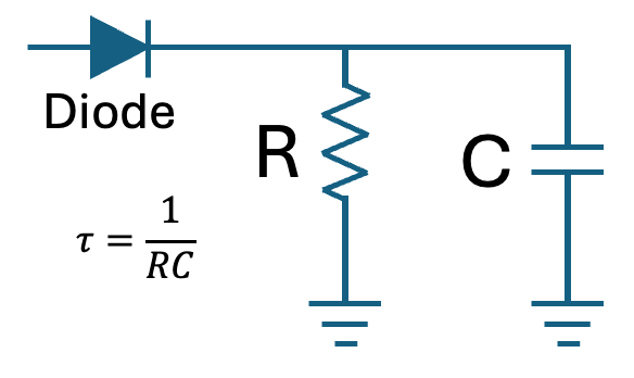
As its name suggests, an envelope detector is used to detect and recover an envelope from an AM signal. Schematically, it consists of a diode followed by a capacitor and resistor, which together form a lowpass filter. The diode rectifies the negative half-cycles of the AM signal, leaving only the positive half. The lowpass filter then smooths out the envelope signal and eliminates the high frequency carrier components.
Sometimes the signal environment is noisy. For example, a typical AM radio receives dozens of modulated signals at different carrier frequencies. The envelope detector described above has no frequency selectivity; it will process all signals simultaneously. For this reason, the detection setup often incorporates a bandpass filter to isolate the carrier signal before passing it to the envelope detector, although strictly speaking, this is not a feature of the envelope detector itself.
Where are envelope detectors used?
Envelope detectors are common in any application where the amplitude of a signal contains useful information. This is true for RF, communications, optics, sensing, and control. Common applications include:
- AM demodulation: Recovering the information encoded in the amplitude of an RF carrier.
- Pulse detection: Determining when a pulse or burst starts and ends without tracking every cycle.
- Optics and photonics: Extracting the amplitude modulation of a photodetector signal in spectroscopy or interferometry experiments.
- Quantum optics: Extracting the amplitude of a photodetector signal to provide real-time indication of resonance strength in cavity and laser stabilization experiments.
- Ultrasound or radar: Extracting the amplitude profile of reflected pulses, which could correspond to targets.
- Control systems: Using the amplitude of an oscillation as a control variable.
- Condition monitoring: Tracking vibration or acoustic envelopes to identify repetitive impacts.
- Audio: Measuring amplitude for compressors, limiters, level meters, and more.
For every experiment, the envelope detector design parameters depend on the application at hand. There is no universal envelope detector that would work for each of these use cases, and the bandwidth, response time, filtering, and trigger behavior all must be tailored to the signal and desired result.
Envelope detector design considerations
There are two major design considerations when creating an envelope detector. The first is whether a bandpass filter should be used, and then choosing one that isolates the narrow band around the desired carrier frequency.
The second consideration is the choice of lowpass filter within the envelope detector. The time constant tau of the RC circuit, equal to the reciprocal of the capacitance times the resistance, must be chosen to minimize distortions. For best performance, the time constant should satisfy the following condition:
Where fcarrier is the carrier frequency, fmax is the bandwidth of the data contained in the envelope, and =1/(RC). This allows the envelope to pass through the circuit while ensuring there is no leakage of the carrier signal.
Envelope detector implementations
There are three ways implement an envelope detector:
- Physically construct an envelope detector using a PCB and standard circuit components. Since the individual components that comprise an envelope detector are not expensive, it is often faster and cheaper to simply solder the components onto a PCB and insert the device directly into the setup. Moreover, this option does not require the end user to have coding experience.
While cheap and fast, a physical detector like this cannot change once the components are soldered in place. For setups that need active control over the filter shape, center frequency, or time constant, this method is inflexible and does not allow for any configurable processing. For example, if the carrier frequency or bandwidth varies, a fixed analog circuit would not be able to address changing signal parameters.
- Implement digital signal post-processing and filtering. This is also very easy to set up, especially given the readily available software packages for digital filtering. This method can improve accuracy and precision, giving users total control over filter parameters and shaping.
However, this comes at the cost of real-time analysis. Given the nature of computer-based DSP, the data must be collected in discrete traces and analyzed later. If the experiment requires low latency or if the signal feeds a trigger or feedback loop, software post-processing may be too slow. Continuously calculating the amplitude in hardware would allow for real-time data extraction.
- Deploy in real-time on FPGA. This offers a blend of advantages of the previous two methods, implementing the DSP on hardware with ultra-low latency and deterministic timing, while retaining the reconfigurability and control over filter parameters. An FPGA can also perform other analysis and DSP functions in parallel.
While real-time digital filters and envelope detectors can be the most flexible option, they often have the highest barrier to entry. The tools and skills required to efficiently program an FPGA are difficult to acquire, even when customizing the envelope detector to the signal at hand is important. Customization may even be the only practical path forward for applications such as:
- The carrier or beat frequency is unique to the experiment.
- The modulation bandwidth may change during a scan.
- The useful signal may be very small relative to detector noise.
- You may need a specific response time.
- You may need to trigger when the envelope crosses a threshold.
- You may need to use the envelope directly in a feedback loop.
- Multiple channels may need to be processed simultaneously.
All of these applications require additional logic, real-time adjustments, or specific parameter settings that are difficult, if not impossible, to implement without customization. However, creating a custom instrument or signal processing capability is now faster and easier than ever, allowing users to define the feature with natural language, no FPGA programming required.
What is Generative Instrumentation?
Rather than having to construct a physical filter on your bench, or develop your own firmware, Generative Instrumentation (GenInst) allows engineers to define:
- Inputs
- Outputs
- Filter shape and bandwidth
- Timing requirements
- State behavior
using natural language. Once defined, the user walks through a guided specification process to fully scope project requirements. GenInst then designs, tests, and builds the custom envelope detector instrument that’s ready to deploy to reconfigurable Moku hardware.
For example, an engineer working in quantum optics could tailor their envelope detector to the current experiment instead of building filters from discrete components by hand every time. They would prompt,
“Extract the envelope of a photodetector beat signal, apply configurable filtering, and generate a trigger when optical coupling or interference contrast calls below a user-defined threshold.”
In minutes, they would have a real-time optical beat amplitude monitor. Typically, building this capability would require manually designing the signal processing chain, selecting an envelope detection method and filter architecture, and writing the FPGA logic to execute it in real time. The engineer would need to define fixed-point data widths and scaling, tune filter parameters for the expected beat frequency and modulation bandwidth, implement threshold and trigger logic, and then simulate and validate the design before deploying it to hardware. Any change to the experiment, such as a different beat frequency, response time, or trigger condition, would require modifying the HDL, rebuilding the test bench, recompiling the design, and validating it all over again.
Building envelope detectors isn’t novel or inherently difficult, but the time required to implement them for advanced research and experimentation takes valuable time and resources away from the experiment at hand. By offloading the task of building custom measurement capability to GenInst Studio, engineers can shift their focus back to their projects and away from managing the instrumentation and electronics required to get valuable results.
How to build a custom envelope detector with GenInst
Prompt:
“Build a two-stage envelope detector that can be used for AM demodulation, within typical AM radio ranges. The first stage should be an adjustable bandpass filter for isolating the carrier, with adjustable center frequency. This stage should be enabled and disabled by a runtime register. The second stage should be an envelope detector, with an adjustable lowpass filter after rectification. The resulting signal should be sent to OutputA.”
Describe the requirements in plain language. In this case we have included an optional bandpass filter stage, which can help to isolate signals of interest and give a cleaner amplitude estimate.
GenInst then asks questions and gathers context, defining the instrument specifications and requirements with your input through a collaborative process.
Build, validate, and iterate. GenInst builds a comprehensive plan including instrument documentation, edge case handling, and a full testbench to validate the instrument. Once you approve, it begins agentically building, testing, and improving the instrument.
Deploy to Moku alongside pre-built instruments; your instrument is now hardware-deployed and fully disconnected from AI, meaning your results are truly deterministic.
Instrument requirements
The instrument was designed to:
Filter an incoming signal
The signal passed to InputA is first fed to a bandpass filter. This stage features adjustable center frequency and bandwidth. This step is optional if the input signal is already clean, if the beat frequency may move substantially, or if you want to assess amplitude across a wide frequency range. However, by making the filter runtime-configurable, this envelope detector can work for a variety of signals.
Rectify and extract the envelope
The next stage recovers the envelope from the AM signal, using digital analogs of the components described earlier. A runtime-adjustable time constant helps the end user find the “sweet spot” for filtering.
Support instrument synchronization
The envelope signal can be routed to:
- An external microphone (for AM radio signals)
- Moku Oscilloscope or Data Logger
- Additional acquisition systems
Once deployed, the final instrument is not just a direct translation of the original prompt. In this example dialogue, GenInst made instrument design suggestions beyond the original prompt. GenInst suggested:
- Covering the entire medium-wave AM region
- Making the bandpass filter adjustable
- Tuning the range of the post-rectifier lowpass filter
GenInst acts as a collaborative design assistant rather than a simple code generator, capturing intent but providing suggestions and best-practices throughout the development process. You don’t need to be an expert in the instrument you’re building to achieve a quality result.
Example configurations
Creating the instrument is only the first step.
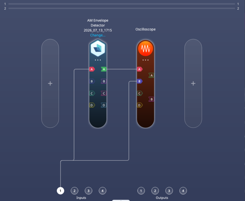
AM radio monitoring. In this setup, the physical Input of the Moku receives the AM signal and passes it to both the AM envelope detector as well as the Oscilloscope instrument. This allows you to view the raw signal from the antenna and the envelope signal side-by-side in real time.
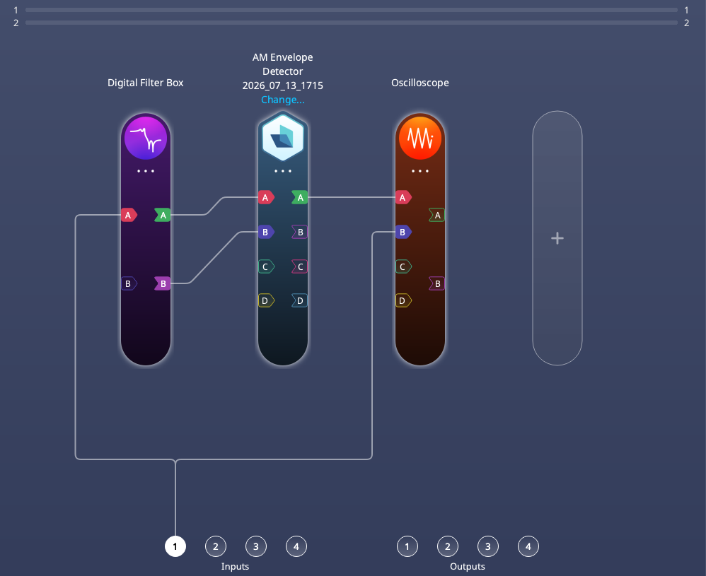
Adding custom / optional filtering. If you require custom filter shaping or signal conditioning, you can disable the AM envelope detector’s bandpass filter and implement your own via the many options available on the Moku Digital Filter Box.
Conclusion
For this application, using GenInst led to significant time and effort savings, as well as a more flexible final product. Development time dropped from a multi-week FPGA effort to a same-day GenInst Studio session. The engineer wrote no HDL, no driver code, and no GUI. The envelope detector runs deterministically on Moku hardware with the same characteristics the engineer would have built by hand. More broadly, every instrument generated by GenInst Studio is versioned and shareable. The next project that requires the user to implement custom filtering or envelope detection can iterate on previous designs and rapidly create new custom instruments.
To try GenInst Studio for free now, sign up for a trial here.