






Overview
Liquid Instruments’ Moku Cloud Compile (MCC) tool enables users to design custom instruments for implementation on Moku platforms. Compared to CPU and application-specific integrated circuit (ASIC) based DSP approaches, FPGAs provide ASIC-level input-to-output latency while being software-defined and reprogrammable like a CPU. FPGA programming is typically done with hardware description language (HDL). The learning curve for HDL coding can be steep compared to software programming languages, but there are a few tools available to convert scripts in other programming languages to HDL. We covered how to use MathWorks HDL coder to convert a MATLAB script into HDL code for implementation on a Moku:Pro in Part I of the tutorial, in this Part II we will demonstrate how to generate HDL code from a Simulink model. Simulink is a graphical-based modeling tool developed by MathWorks. The block diagram-based design philosophy streamlines the process of translating a hand-drawn digital signal processing (DSP) system into a computer-based model. The virtual test and measurement instruments, such as waveform generators and oscilloscopes, provide a more intuitive way to construct the testbench and validate the DSP model. In addition, users have the option to use Simulink to build a fixed-point system from the ground up. Some of the logic operations are easier to implement with MATLAB functions, in this case users can add MATLAB function blocks into their design. For more complicated systems, utilizing both tools could significantly streamline the design process. In this tutorial, we will construct a two-channel Schmitt trigger. The basics and concept design of the Schmitt Trigger can be found Part I of the tutorial. For the first channel, we will use the exact same MATLAB function from Part I of the tutorial to construct the DSP. For the second channel, we will use a Simulink built-in DSP block to achieve the same function.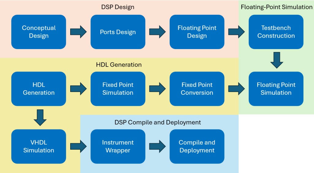 Figure 1: Recommended workflow for Moku Cloud Compile + HDL Coder DSP Design.
Requirements
Before we get started with building and implementing the Schmitt trigger, please ensure your system satisfies the following requirements. For generating VHDL code from a Simulink model you will need to have MATLAB with Simulink, HDL Coder, and Fixed-Point Converter. Note: Mac users will also need to have XCode installed for MATLAB to generate the VHDL code. For compiling the VHDL code you will need to have access to Moku Cloud Compile. For implementing the compiled instrument bitstream, you will need to have a Moku:Pro running firmware version 601 or above, the Moku: app, and access to Multi-Instrument Mode on your Moku:Pro.Design and construct the DSP
Adjust the template
The first step in creating our model is to adjust the Simulink template to fit our DSP design. As our design is a two-channel system, we will only need the InputA, InputB, OutputA, and OutputB ports.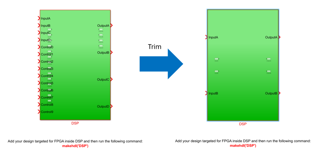 Figure 2: Remove the redundant channels.
Floating-point DSP design
In this section we will construct the two Schmitt triggers, with the first channel using a MATLAB function block and the second channel using a Simulink trigger block. Simulink building blocks can be found in the “Library Browser” under the simulation tab. The search function is the best way to find the desired element. Please note that not all Simulink blocks support HDL code generation. We recommend only using blocks under the “HDL Coder” or “HDL Support” catalog for everything within the DSP subsystem.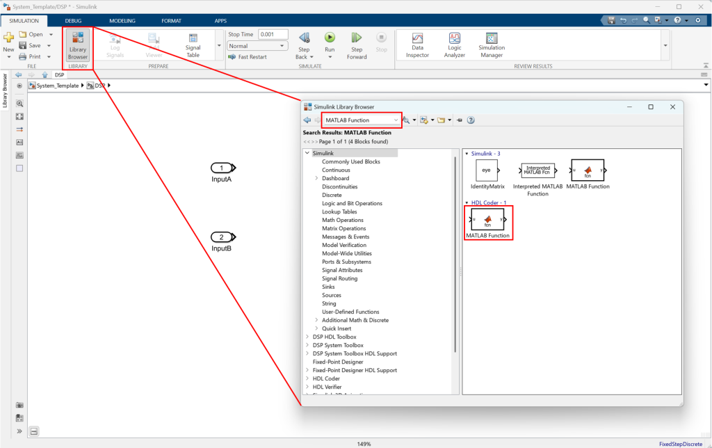 Figure 3: Simulink building blocks can be found via the Library Browser.
 Figure 4: Block diagram design of the MATLAB function-based Schmitt trigger.
function OutputA = Schmitt_Trigger(InputA)
%#codegen
persistent out0; %Retains variable value between function calls.
if isempty(out0) %Initialize the value for the first call.
     out0 = 0;
end

upperThreshold = floor(2^15/10); %Set the upper threshold to 1/10 of the full positive range.
lowerThreshold = -floor(2^15/10); %Set the lower threshold to 1/10 of the full negative range.

if InputA >upperThrehold %Logic to perform the Schmitt trigger function.
     out0 = 2^15-1; %Map to the highest positive number.
elseif InputA <lowerThreshold
     out0 = 0;
end

OutputA = out0; %Assign variable out0 to OutputA.
For the second channel, we will use Simulink’s “Relay” block to perform the Schmitt trigger logic. We placed the relay block between InputB and OutputB, then double-clicked the “Relay” block to change the switch on and off thresholds to floor(2^15/10), and – floor(2^15/10), respectively. In the “Signal Attributes” tab, set the signal output to fixdt(1, 16,0) to match the output.
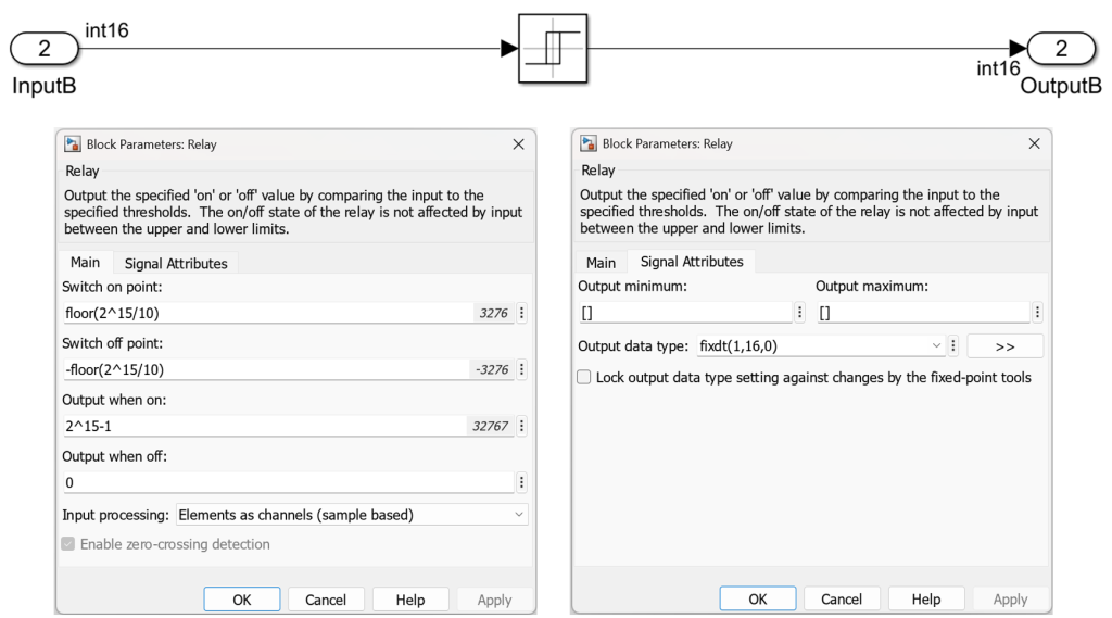 Figure 5: The “Relay” block was set to perform the same Schmitt trigger logic as the first channel.
Construct the testbench
Simulink has a built-in signal generator, oscilloscope, and other common test and measurement equipment blocks. This allows us to design the testbench in a more intuitive way. Please note the building blocks outside of the DSP system do not need to be supported by HDL Coder, as they will be used for simulation only. To construct the testbench, we used a “Signal Generator” block to produce the same signal we used for the testbench in Part I. We rescaled and converted the signal from the generator to match the 16-bit signed input for our system. Before feeding the signal into the Inputs, an additional “Convert” block was added to convert the floating-point numbers to fixed-point. Then, we fed the generator signal, OuputA, and OutputB into the oscilloscope to observe the system response.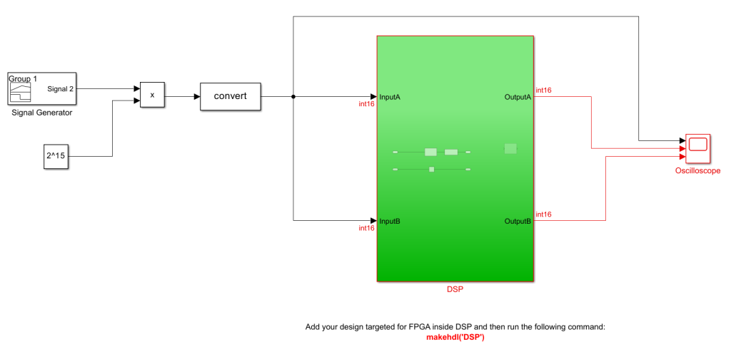 Figure 6: Block diagram of the Simulink-based testbench.
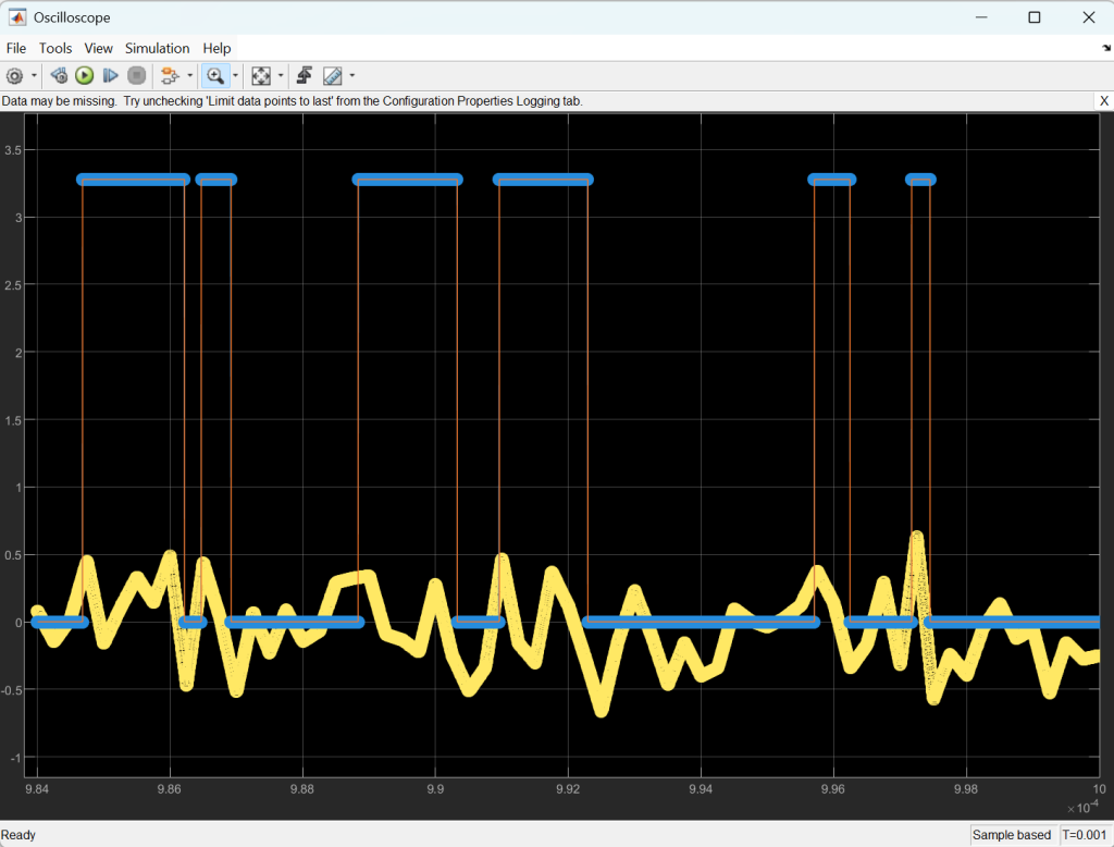 Figure 7: The output of the DSP subsystem on the Oscilloscope.
Fixed-point conversion
Before generating the VHDL code for our DSP subsystem, we will need to convert the floating-point MATLAB function block to a fixed-point function block. We achieve this using MathWorks’ Fixed-Point Tool in the “Apps” tab, with “Iterative Fixed-Point Conversion” method. Please note that if we build the Simulink model with fixed-point DSP from the beginning, we do not have to run the fixed-point conversion.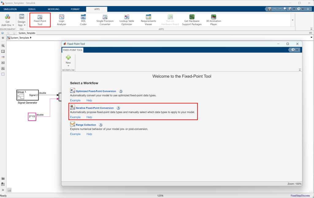 Figure 8: Iterative Fixed-Point Conversion can be initiated via the Simulink Apps tab.
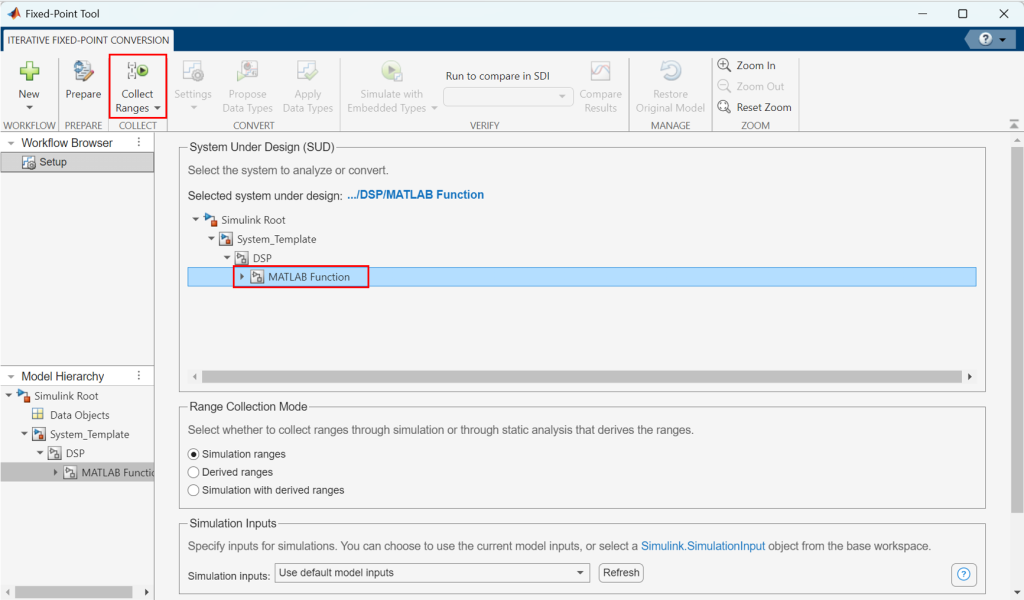 Figure 9: The MATLAB function was selected as the “System Under Design.”
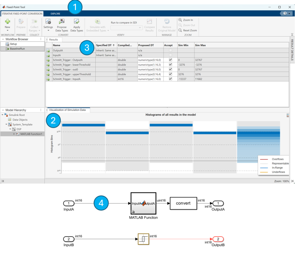 Figure 10: (1) Propose the signal precision based on the testbench data; (2) Observe the signal range with the histograms; (3) Proceed to convert the model to fixed-point design. (4) Delete the first “convert” block.
Fixed-point model verification
After the models have been converted, it is important to run another round of simulation to make sure the behaviors and precision loss are as expected.VHDL code generation
HDL code can be generated by clicking the “Generate HDL Code” button under the HDL Code tab. HDL Coder generation settings are already preconfigured in the Simulink template, therefore we do not need to adjust settings here. Figure 11: “Generate HDL Code” button is located under the HDL Code app.
VHDL simulation with a third-party tool (Optional)
VHDL testbench file can be generated by clicking the “Generate Testbench” button under the HDL Code app. The verification step is identical to the MATLAB example. Figure 12: “Generate Testbench” button is located under the HDL Code app.
DSP Compile and Deployment
Moku Cloud Compile has a standard wrapper built-in to allow the custom instrument to interact with the other parts of the Moku:Pro. The standard wrapper uses all four input channels and output channels for the instrument; this does not match our Schmitt trigger example, which has two inputs and two outputs. Therefore, we will need to create a custom wrapper for the instrument from the provided template. Please note even with the “Minimize clock enables” option selected, sometimes HDL Coder still generates VHDL code with clock_enable and ce_out ports (like in this tutorial). We will connect the clock_enable with a constant high signal and leave the ce_out ports open if these ports are created during the VHDL conversion process.
ARCHITECTURE HDLCoderWrapper OF CustomWrapper IS
-- SIGNAL Declarations
SIGNAL ConstantHigh:std_logic.        :='1';
--Component Declarations
COMPONENT DSP
PORT(Clk                              : IN std_logic;
     Reset                            : IN std_logic;
     clk_enable                       : IN std_logic;
     InputA                           : IN signed(15 DOWNTO 0); -- sfix16_En16
     InputB                           : IN signed(15 DOWNTO 0); -- sfix16_En16
     ce_out_0                         : OUT std_logic;
     ce_out_1                         : OUT std_logic;
     OutputA                          : OUT signed(15 DOWNTO 0); -- sfix16_En14
     OutputB                          : OUT signed(15 DOWNTO 0); -- sfix16_En14
     );
END COMPONENT;

BEGIN
     u_DSP:DSP
          PORT MAP(Clk => Clk,
               Reset => Reset,
               clk_enable => ConstantHigh,
               InputA => InputA,
               InputB => InputB,
               ce_out_0 => open,
               ce_out_1 => open,
               OutputA => OutputA,
               OutputB => OutputB
          );
END HDLCoderWrapper;
Compiling and deploying the instrument
Detailed instructions on how to use Moku Cloud Compile to build instrument bitstream and deploy the instrument can be found in our Moku Cloud Compile Getting Started Guide. To compile the Schmitt trigger, create a new project on Liquid Instruments’ Moku Cloud Compile. In this project, create a file for the DSP_fixpt.vhd, which is the VHDL code for the Schmitt trigger; also create a wrapper file for the custom wrapper from the previous sections. Select a target device as a Moku:Pro with 4 slots and build the project. Once the bitstream is built, you will be able to deploy the Schmitt trigger on your Moku:Pro using the web interface and the Moku: app. To demonstrate the Schmitt trigger is functioning as per our conceptual design, we implemented the instrument on a Moku:Pro using the Moku: App and Multi-Instrument Mode. In slot 1, we placed in an Arbitrary Waveform Generator to generate the same signal we have used in the testbench as the input signal to the Schmitt trigger. In slot 2, we placed in our Schmitt trigger. In Slot 3, we placed in an Oscilloscope to compare the output signals from the Schmitt trigger and the Arbitrary Waveform Generator. We first verify the Schmitt trigger in Channel A designed with the MATLAB function block. We can confirm the output from the Schmitt trigger is switched to high when the input signal is above 110 mV and waited until the signal is dropped below -110 mV to switch to zero.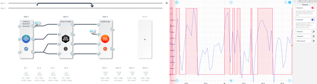 Figure 13: (a) Multi-instrument system configuration for testing the MATLAB function bloc Schmitt trigger. (b) Oscilloscope measurement verifying the Schmitt trigger is functioning as designed.
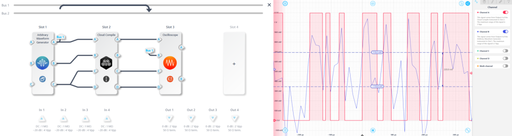 Figure 14: (a) Multi-instrument system configuration for testing the Simulink trigger block Schmitt trigger. (b) Oscilloscope measurement verifying the Schmitt trigger is functioning as designed.
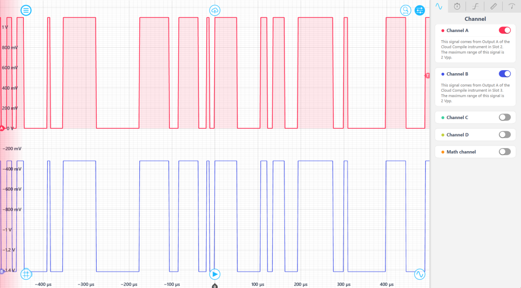 Figure 15: The Schmitt trigger designed using the MATLAB function block and the trigger block have the same behaviors.