






A quick introduction to frequency mixing
Transmitting information via microwaves pulses requires a combination of speed and precision in control electronics. While microwave sources can generate a coherent, stable signal over GHz ranges with low phase noise, they are limited by low switching speed, often on the order of milliseconds. They also typically lack the ability to shape pulses. Arbitrary waveform generators (AWGs), on the other hand, offer excellent resolution and control over the shape of the output waveform. While they are useful for designing and playing back pulse envelopes, most AWGs are limited by speed. With the digital-to-analog converters (DAC) often in the range of a few GSa/s, they are unsuitable for directly generating microwave signals above 1 GHz.
Frequency mixing is a technique that can leverage the strengths of both devices. Using a mixer, a passive component that multiplies two components together, the AWG can arbitrarily shape the microwave carrier frequency, forming high-frequency pulses.There are two types of frequency mixers: 3-port mixers and four-port (IQ) mixers, both illustrated in Figure 1. Both types operate in the same way, multiplying the input (called the intermediate frequency, or IF) by the local oscillator (LO). The mixer then emits the combined signal from the RF port. Mixers also work the same way in reverse, combining the RF port with the LO. An IQ mixer is a more complex design which takes two inputs, I and Q, and mixes each of them with the LO separately before combing them. In the next section, we will discuss the advantages of this method.
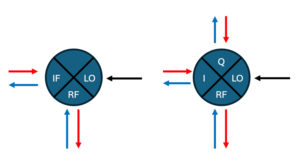
Figure 1. Diagram of a frequency mixer. An IQ mixer consists of two separate 3-port mixers and a signal adder. Mixers are passive components that can upconvert (red arrows) or downconvert (blue arrows) by combining the input with a LO.
IQ mixer operation
Imagine an AWG generates sine wave of low frequency ω_IF and amplitude B. This signal passes to the IF port of a 3-port mixer, where it combines with a LO of frequency ω_LO and amplitude A. The mixer outputs the product of these two signals, given by
\(A \sin{(\omega_{LO}t)} \times B \sin{(\omega_{IF}t)} \) (1)
We use the sine multiplication identity:
\(AB \left[ \sin{(\omega_{LO}t)} \sin{(\omega_{IF}t)} \right] = \frac{AB}{2} \left[ \cos{((\omega_{LO}-\omega_{IF})t)}- \cos{((\omega_{LO}+\omega_{IF})t)} \right]\) (2)
Note that the LO amplitude, represented by A, is typically fixed. The baseband waveform amplitude B thus effectively turns on and off the mixed signal product, allowing it to form short pulses by gating the LO output. We also see that the result has two products, one at frequency \(\omega_{LO} – \omega_{IF}\) and the other at \(\omega_{LO} + \omega_{IF}\). These are called the lower and upper sidebands, respectively. The presence of two frequency components can have adverse effects if they are nearby in frequency space, particularly in information-dense systems such as quantum computing and communications. Fortunately, one of the sidebands can be suppressed through IQ mixing.
When using a four-port IQ mixer, we generate two phase-synchronous outputs from the AWG, \(B \sin{(\omega_{IF}t)}\) and its counterpart \(B \cos{(\omega_{IF}t)}\). The IQ mixer takes each input and mixes them separately, with a phase shift of the LO by 90 degrees before mixing with Q. In this case, the product of the I port remains the same as before (Eq. 2):
\(AB \left[ \sin{(\omega_{LO}t)} \sin{(\omega_{IF}t)} \right] = \frac{AB}{2} \left[ \cos{((\omega_{LO}-\omega_{IF})t)}- \cos{((\omega_{LO}+\omega_{IF})t)} \right]\)
The Q product, when mixed with the phase-shifted LO, produces a similar result:
\(AB \left[ \cos{(\omega_{LO}t)} \cos{(\omega_{IF}t)} \right] = \frac{AB}{2} \left[ \cos{((\omega_{LO}-\omega_{IF})t)}+ \cos{((\omega_{LO}+\omega_{IF})t)} \right]\) (3)
The products are combined via a signal adder. When the I and Q terms add together, the terms proportional to \(\cos(\omega_{LO}+\omega_{IF})t \) have opposite signs and thus cancel, removing the upper sideband.
\(\frac{AB}{2} \left[ \cos{((\omega_{LO}-\omega_{IF})t)}- \cos{((\omega_{LO}+\omega_{IF})t)} \right] + \frac{AB}{2} \left[ \cos{((\omega_{LO}+\omega_{IF})t)}+ \cos{((\omega_{LO}-\omega_{IF})t)} \right]\)
\(= AB \cos{((\omega_{LO}-\omega_{IF})t)}\) (4)
For this to be the case, the amplitude of the I and Q waveforms must match and have exactly 90 degrees of phase shift between them. Often in real life systems, it is sufficient to minimize the sideband to an acceptably low power level. To choose the other sideband instead, replace the Q baseband waveform \(\cos(\omega_{IF}) \) with \(-\cos(\omega_{IF}) \). This reverses the signs in Equation 4, causing the lower sideband terms to cancel and preserving the upper sideband.
Mixers are passive and can operate in reverse, removing the high-frequency component from an RF signal and returning the baseband (IF) signals. For the next example, assume we have an upconverted signal with components \(\omega_{LO}\) and \(\omega_{IF}\), and that we have suppressed the lower sideband, leaving only \(B \cos{((\omega_{LO}+\omega_{IF} )t)}\). We then demodulate by passing the signal into a mixer, using the same LO:
\(AB \left[ \cos{((\omega_{LO}+\omega_{IF})t)} \cos{(\omega_{LO}t)}\right] = \frac{AB}{2} \left[ \cos{((2\omega_{LO}+\omega_{IF})t)}+ \cos{(\omega_{IF}t)} \right]\) (5)
Like with the upconversion case, we get two frequency components, \(2\omega_{LO}+\omega_{IF}\) and \(\omega_{IF}\). The high frequency component is typically filtered out using a lowpass filter to avoid aliasing at the ADC, keeping only the baseband waveform \(\cos{(\omega_{IF} t)}\). A four-port IQ mixer will also return the sine component, by mixing the input with a phase-shifted LO signal:
\(AB \left[ \cos{((\omega_{LO}+\omega_{IF})t)} \sin{(\omega_{LO}t)}\right] = \frac{AB}{2} \left[ \sin{((2\omega_{LO}+\omega_{IF})t)}-\sin{(\omega_{IF}t)} \right]\) (6)
Similarly filtering this output will result in the full amplitude and phase profile of the signal, which can be seen in the next section.So far in these math examples, we have omitted phase factors. In Equation 6, for example, adding a phase factor to the RF term would result in a phase offset for the baseband signal. As long as the phase of the LO remains stable when upconverting and downconverting, this is not a problem. Maintaining a stable LO phase is typically accomplished by using two synchronized LO channels, or a signal splitter. Downconverting with the same LO removes the global phase, and only the phase difference introduced by the setup (i.e. the DUT) will remain in the final baseband signal.
Detecting high frequency signals with undersampling
A frequency mixing setup requires this additional downconversion step if the bandwidth of the analog-to-digital converter (ADC) cannot encompass the entire signal profile. For example, an oscilloscope rated for 1 GHz analog bandwidth would heavily attenuate a 6 GHz signal of interest, thus requiring an intermediate frequency stage.Moku:Delta has a sampling rate of 5 GSa/s and a stated bandwidth of 2 GHz. The frontend contains a lowpass filter which attenuates any input frequencies above 2 GHz, but also offers the option to route the input signal directly through a balun* instead. This feature allows users to access the full analog bandwidth of the Moku:Delta ADC, for viewing with various Moku instruments such as the Spectrum Analyzer or Lock-in Amplifier.At 5 GSa/s, Moku:Delta’s first Nyquist zone ranges up to 2.5 GHz, and signals at higher frequencies will fold into the range from 0 to 2.5 GHz. This process, known as undersampling, effectively acts as a mixer, downconverting signals at a specific frequency to one within Moku’s frequency range. Phase information is preserved if the generation and detection clocks are synchronized. As we will see in the next section, this can be achieved by synchronizing the microwave source to the clock of Moku:Delta.
For more information about 6 GHz mode for Moku:Delta, see the application note on the topic.
*a balun simply converts the unbalanced RF signal to a balanced differential signal for the Moku’s ADC
Frequency upconversion using the Moku Arbitrary Waveform Generator
In this section, we show how Moku:Delta can be used with a microwave synthesizer to generate pulses above 2 GHz. For this test, we require an external IQ mixer, microwave source, and bandpass filter. The setup is illustrated in Figure 2. The Moku:Delta analog outputs are connected to the I and Q ports of the mixer, and the LO is provided by an external microwave source. After the upconversion, the signal is routed through a bandpass filter and directly looped back to the Moku:Delta’s analog input, without an intermediary downconversion stage. Moku:Delta’s 10 MHz Ref Out connects to the 10 MHz input of the microwave source, synchronizing the two to Delta’s clock.
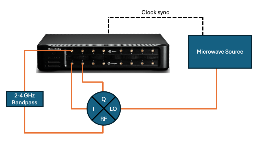
Figure 2. Example connection diagram. Moku:Delta provides the baseband waveforms and demodulation stage. A microwave source generates the LO.
In the Moku app, we configure the Moku:Delta in three-slot mode, with the Lock-in Amplifier, Spectrum Analyzer, and Arbitrary Waveform Generator in slots 1, 2, and 3, as seen in Figure 3 below. The Arbitrary Waveform Generator outputs connect to analog outputs 1 and 2, while analog input 1 routes the signal to both the Lock-in Amplifier and Spectrum Analyzer. We ensure that the analog bandwidth is set to 6 GHz by clicking on the port number.
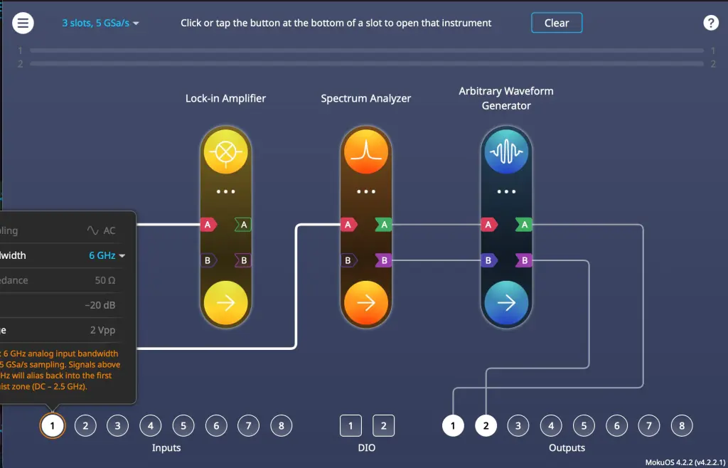
Figure 3. Multi-Instrument Mode configuration for Moku:Delta frequency mixing.
The microwave generator uses its own proprietary software, provided with the device. We set the center frequency to 4 GHz and the RF power to +13 dBm (in accordance with the specifications of the mixer data sheet).
We now use the Moku Spectrum Analyzer to verify the operation of the mixer. After opening the instrument, we view the range from 1 to 2 GHz. We enable the RF power on the microwave source. In the 6 GHz bandwidth mode, Moku:Delta samples the input signal at 5 GSa/s, meaning that the 4 GHz signal generated by the microwave source will fold into the first Nyquist zone, appearing at 1 GHz. Viewing the spectrum, we can confirm this — some of the LO signal leaks through the mixer at very low power (< -65 dBm), as seen in Figure 4. The presence of the bandpass filter should reduce any harmonics or DC noise, particularly the 8 GHz second harmonic from the microwave source that folds to 2 GHz.
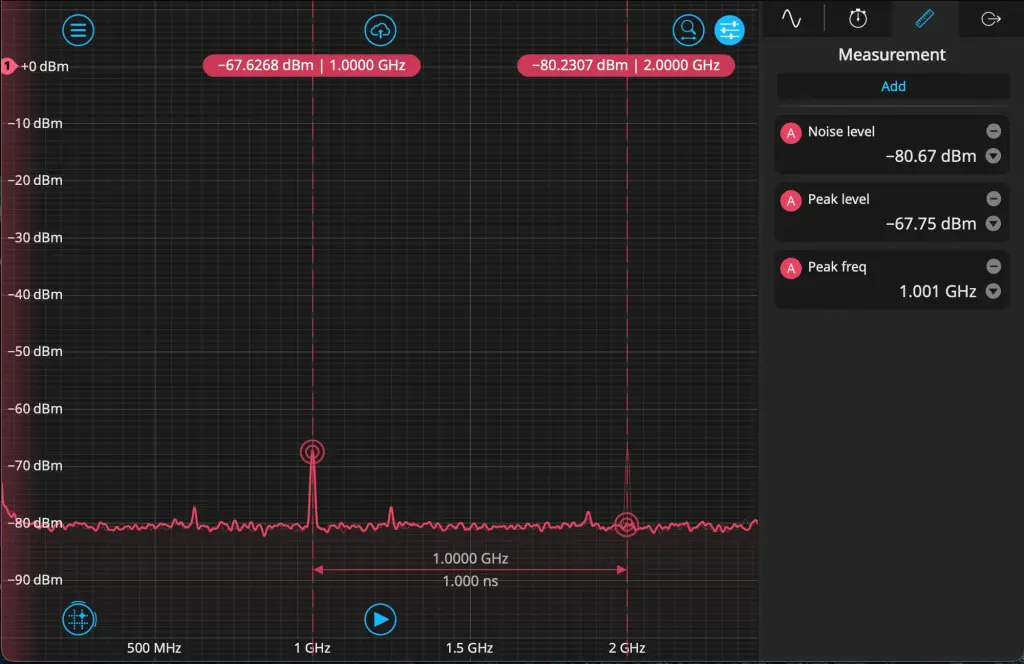
Figure 4. Spectral profile of the LO. The 4 GHz LO signal appears at 1 GHz when undersampled. With no baseband signal, only a small amount of the LO leakage through the mixer is visible. The bandpass filter heavily attenuates signals outside the range of 2 to 4 GHz.
We now open the Arbitrary Waveform Generator instrument to configure our baseband pulses. Set the repetition rate to 100 kHz and the amplitude to 1 Vpp. Using the equation editor, divide each waveform into four sections. Set the equations for each section as follows:
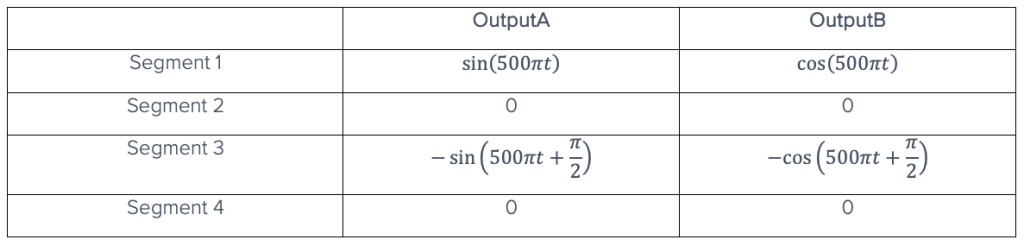
This sequence should produce two 25 MHz pulses of 2.5 μs, with the second pulse shifted by 90 degrees relative to the first. This can be seen in Figure 5. As shown at the beginning of the note, adding the cosine terms on OutputB will suppress the upper sideband when mixing. Enable both of the outputs.
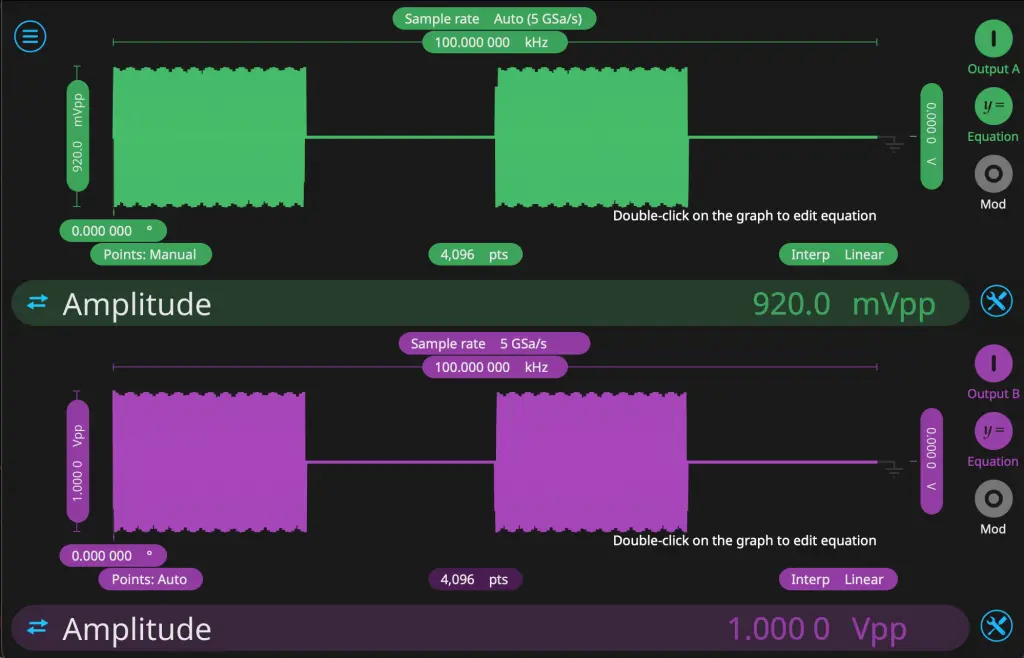
Figure 5. Arbitrary Waveform Generator configuration for IQ mixing. The amplitudes of the baseband waveforms are adjusted to minimize the upper sideband.
Return to the Spectrum Analyzer instrument to view the spectral profile of the upconverted signal. We are using the Arbitrary Waveform Generator to produce a baseband signal at 25 MHz, which is mixed with the 4 GHz LO from the microwave source. This produces sidebands at 4.025 GHz and 3.975 GHz, which alias to 975 MHz and 1.025 GHz, respectively. The sideband at 1.025 GHz (corresponding to the lower sideband of 3.975 GHz) should be greatly reduced. If both sidebands are still prominent, there may be a phase or amplitude mismatch between I and Q. This is common with analog mixers and depends on the exact attenuation and phase shift of the cables and mixer itself. Adjust the amplitude of the I or Q waveform and view the result on the Spectrum Analyzer. When the amplitudes are well matched, the frequency component at 1.025 GHz will reach a minimum power and begin to rise again when the amplitudes are mismatched. As seen in Figure 5, the upper sideband was minimized when the I and Q amplitudes were 920 mV and 1 V, respectively.
After calibration, we are left with the upper sideband of 4.025 GHz, which appears in the first Nyquist zone at 975 MHz, as seen in Figure 6. In the next section, we will show how the Moku Lock-in Amplifier can be used to demodulate the pulses that we have generated.
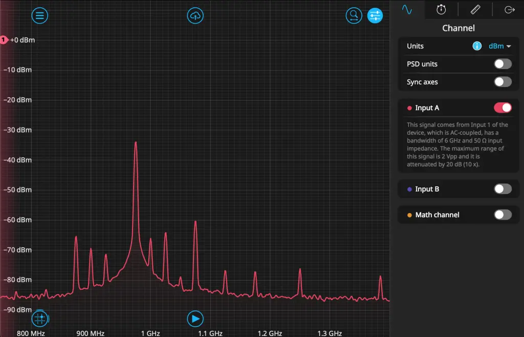
Figure 6. Spectral profile of the upconverted pulses. The main component is present at 975 MHz, where 4.025 GHz folds in the Nyquist zone. The LO leakage at 1 GHz remains low amplitude, and the upper sideband at 1.025 GHz is minimized (corresponding to 3.975 GHz).
Phase detection with the Moku Lock-in Amplifier
We can now demodulate the signal. Since the signal is sampled at 5 GSa/s, the pulses appear identical to those at 975 MHz. In this range, we can use the Moku:Delta LO to demodulate, since its internal clock is synchronized with that of the microwave generator.
Open the Lock-in Amplifier window and set the LO to 975 MHz. The phase shift of the LO is arbitrary in this case, as it only shifts the absolute values of the measured phase and not the phase difference between the pulses. The lowpass filter should be set high enough that the pulses have relatively sharp edges but with minimal ringing. We set it to 10 MHz with 12 dB/octave rolloff. We also set the demodulation mode to Polar Coordinates, and in the settings menu, we select “Filtered Signal” for the auxiliary output. This will give us both R and θ information after demodulation. Finally, we apply a 30 dB gain boost to R to maximize signal fidelity.
We place a probe point at Out B and view the phase information, capturing a few pulse cycles. There are noisy patches where there is no pulse, and a steady value connecting them that should correspond to the pulses. We add markers and measure the approximate level of these DC voltages. As seen in Figure 7, the difference between them is approximately 250 mV, which corresponds to 90 degrees when converting units (1 V/cyc ratio). See our Knowledge Base article on this topic for details. Adjusting the phase shift number will change the absolute voltage levels, but the difference should remain around 250 mV. This means that our pulse train, alternating between 0- and 90-degree pulses, is extracted again even after a sequence of up- and downconversion.
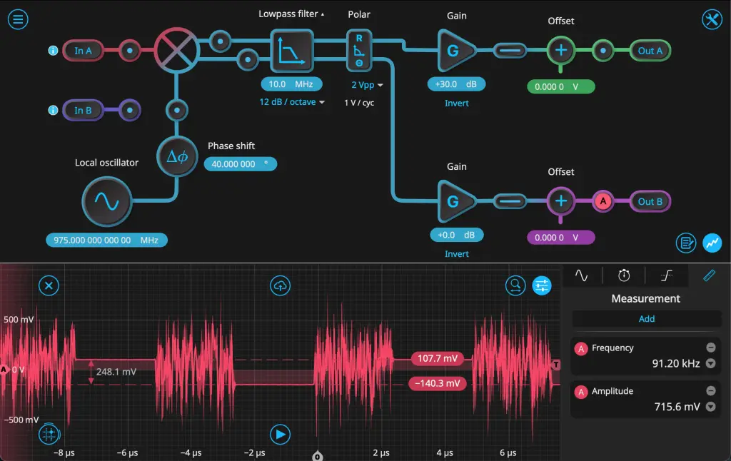
Figure 7. Recovered phase after demodulation. After the signal is mixed at 975 MHz, the R and θ components are recovered. The phase is scaled to a voltage, which when measured gives ~250 mV, corresponding to the expected 90 degrees.
On the Multi-Instrument Mode configuration screen, we replace the Spectrum Analyzer with the Oscilloscope and feed both Lock-in Amplifier outputs to inputs A and B of the Oscilloscope. This allows us to view the R/θ output side-by-side. The pulses on the R trace should be the appropriate length (2.5 μs) and have sharp edges. They should also all be approximately the same height, and the phase difference should be the same as determined in the previous step. We can save this Oscilloscope trace for further analysis.
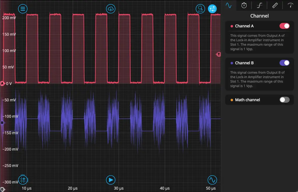
Figure 8. Recovered amplitude and phase after demodulation using the Moku:Oscilloscope.
Conclusion
Extracting phase information from modulated signals is critical for applications such as phase-shift keying (PSK) in communications and qubit readout in quantum information science.
In this work we gave an overview of the basic principles of frequency mixing and demonstrated how Moku:Delta can help generate and detect microwave pulses while simplifying the traditional frequency-mixing setup. We showed how the Arbitrary Waveform Generator could generate baseband pulses, which were then upconverted using an external microwave source and double-balanced IQ mixer.
Finally, we demonstrated how Moku:Delta can directly detect and demodulate the microwave pulses using its 6 GHz analog bandwidth mode. This eliminates the need for analog downconversion while preserving phase information contained in the pulses, making it useful for a variety of applications which require precise phase measurement of microwave frequencies.