






Modern quantum optics applications—such as single-photon generation, quantum memory interfaces, and long-range optical quantum communication—impose stringent requirements on optical bandpass filtering. In particular, bridging microwave and optical frequencies via coherent microwave-to-optical conversion is a cornerstone for distributed quantum technologies and the realization of heterogeneous quantum systems. For instance, itinerant single microwave photons generated by superconducting qubits [1] and single phonons generated by nanostructured optomechanical crystals (OMCs) [2] must be upconverted to telecom wavelengths to exploit the low attenuation of optical fibers for long-distance transmission.
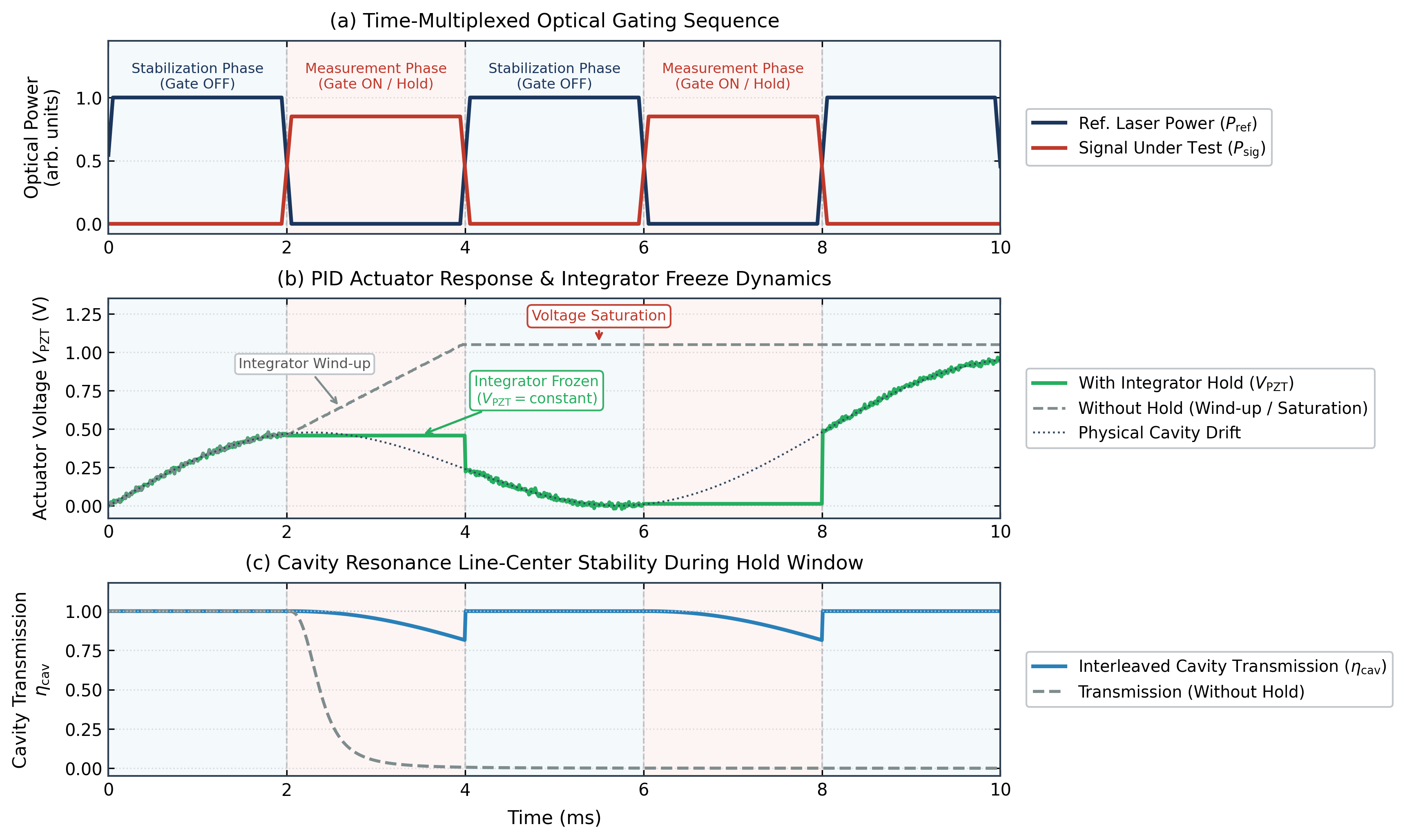
Figure 1. Time-series optical waveforms incident on the cavity during interleaved laser locking and signal measurement. The signal under test and the high-intensity reference laser alternate entering the cavity. (Note: the amplitude of the signal under test is exaggerated for visual clarity; its actual power is extremely low).
In these systems, an optical cavity whose resonance frequency precisely matches the target wavelength provides high-selectivity narrowband filtering, serving as an indispensable device for high-fidelity quantum signal detection. Its critical role is separating extremely weak single-photon quantum signals from the intense pump light used for optomechanical anti-Stokes scattering or electro-optic conversion. Because single-photon signal powers are orders of magnitude lower than the background light, maximizing transmission efficiency while rejecting off-resonant pump leakage is essential to achieving a high signal-to-noise ratio (SNR).
However, optical cavities are inherently susceptible to environmental disturbances such as thermal drift and acoustic/mechanical vibrations, causing their resonance frequencies to drift over time and degrading filtering performance. Consequently, active feedback control techniques—such as Pound–Drever–Hall (PDH) locking or dither locking—are employed to dynamically correct cavity length drift and continuously maintain the target resonance condition.
This introduces a fundamental experimental contradiction: cavity locking requires injecting a relatively strong reference laser into the cavity and measuring the reflected signal to generate a high-SNR error signal, whereas the quantum measurement phase demands an ultra-quiet, dark background. If the reference laser coexists with the single-photon signal, its scattered light will saturate sensitive single-photon detectors (SPDs) and completely drown out the delicate quantum signal under test.
Therefore, it is critical to temporally decouple the cavity stabilization process from the quantum measurement window. Platforms such as quasi-2D OMCs [2] and electro-optic transducers [1] have adopted pulsed protocols such as “load-and-convert” to sustain ultra-low-noise operation. In these architectures, stable cascaded Fabry–Pérot filter cavities must continuously provide high-precision filtering to reject strong pump leakage. Through an interleaved stabilization strategy, the reference light can be extinguished during quantum state conversion and detection while the filtering cavity remains locked on resonance. This simultaneously preserves cavity stability and single-photon detection sensitivity.
The problem
To resolve the fundamental conflict between the high-intensity locking laser and the dark background required for single-photon detection, the system adopts a time-division multiplexing (TDM) interleaved locking strategy. This approach divides the operational cycle into a stabilization phase and a measurement phase. During the stabilization phase, the strong reference laser is briefly coupled into the cavity to update the feedback control. The reference light is then extinguished, allowing only the weak quantum signal to enter the stabilized cavity during the subsequent dark measurement window.
Figure 1 illustrates the time-dependent optical intensity received at the cavity. The experiment employs interleaved optical signal routing, alternating between the signal under test (SUT) and the high-intensity reference laser (Ref. Laser) entering the cavity. The amplitude of the signal under test (red curve) in Figure 1 is exaggerated for visual clarity. In real-world applications, the quantum signal is weak (typically at the single-photon level), orders of magnitude weaker than the strong reference laser. When the signal under test is active, the reference laser is switched off, and the weak optical signal enters the cavity for narrowband filtering before detection, acquisition, and analysis. During this window, the strong reference laser is blocked from the optical path, preventing background scattering from corrupting the delicate signal. When the high-intensity reference laser reenters the cavity the feedback control loop reactivates, using the reference light to generate the error signal required for cavity locking. The controller then adjusts the cavity piezoelectric actuator to continuously align the cavity resonance with the reference laser wavelength. Once the reference laser is extinguished and the path switches back to the signal under test, feedback control enters the hold state, maintaining the cavity near resonance throughout the measurement window. Thus, through periodic reference laser locking and interleaved signal measurement, low-background optical signal detection is achieved while preserving cavity stability.[/vc_column_text][/vc_column][/vc_row]
However, conventional analog proportional-integral-derivative (PID) controllers are fundamentally incompatible with periodic gating signals. Experimental evaluations reveal that when the reference laser is extinguished during the measurement window, analog imperfections (such as DC electrical offset and voltage noise fluctuations) are misidentified by the analog controller as persistent frequency errors. This causes continuous accumulation in the integral term, known as integrator windup. Consequently, the controller drives the piezoelectric actuator with erroneous negative feedback overcompensation, preventing the cavity from maintaining its locked position and destabilizing subsequent measurement windows. Therefore, a digital PID controller is essential to provide exact digital 0 V gating truncation and drift-free feedback output holding.
Furthermore, the switching frequency between the stabilization and measurement phases must be carefully optimized. If the hold window is too long, the system cannot timely compensate for higher-frequency mechanical vibrations and thermal drift, resulting in progressive lock degradation. Therefore, the system requires both high-speed optical routing and a dedicated feedback controller capable of recognizing gate states.
The solution
To avoid integrator windup, this study adopts a track-and-hold PID architecture. The controller receives an enabling signal synchronized with the optical gating and automatically toggles between tracking and hold modes:
- Tracking Phase (Gate ON):The reference laser is on, the error signal is continuously fed into the controller, and the PID controller calculates the feedback voltage in real time to drive the PZT, compensating for cavity length drift.
- Hold Phase (Gate OFF):The reference laser is off, and the signal under test enters the cavity. At this moment, the controller freezes its control output, and the actuator holds its previous position, maintaining the cavity length nearly constant throughout the dark measurement window.
This strategy avoids integral accumulation during the absence of the error signal, enabling the cavity to stay on resonance without illumination from reference light. Figure 2 illustrates the interleaved electro-optic signal routing and cavity stabilization control architecture based on the Moku Laser Lock Box. Moku synchronously controls the optical switch and electrical signal routing, toggling between the SUT measurement mode and the reference laser locking mode.
When the switch control signal is high, the system enters the SUT measurement mode. The cavity’s optical input switches to the SUT, and the transmitted, filtered optical signal is detected and converted to an electrical signal, which is routed to a signal analyzer for measurement. Simultaneously, the feedback control loop enters the hold state, freezing the current feedback output to prevent actuator adjustments from disrupting cavity resonance during quantum signal measurement.
When the switch control signal is low, the system transitions to the reference laser locking mode. The high-intensity reference laser is routed into the cavity for feedback control. The reflection response is routed back to the Moku Laser Lock Box, which generates the error signal and executes feedback control, continuously locking the cavity resonance to the reference laser wavelength. Through synchronized optical and electrical switching, the system achieves interleaved operation of “reference laser locking — feedback holding — signal measurement.”
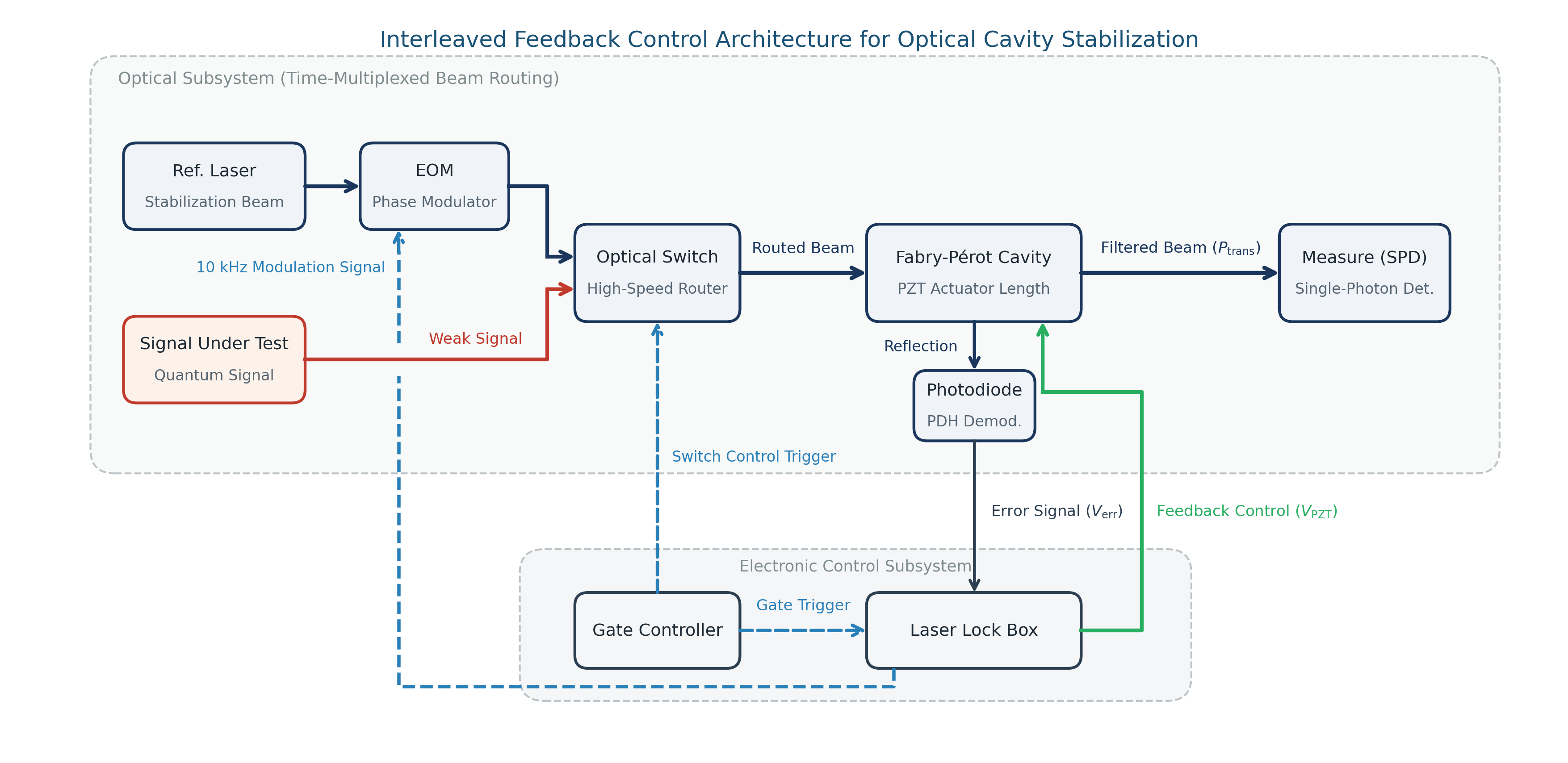
Figure 2. Interleaved electro-optic signal routing and cavity stabilization architecture based on the Moku Laser Lock Box. The switch control signal toggles between signal under test measurement mode and reference laser locking mode.
The result
To validate this interleaved control architecture, the experimental apparatus integrates three functional subsystems: optical cavity, synchronized gating, and feedback control. The optical subsystem employs a Fabry–Pérot cavity whose center wavelength precisely matches the tunable reference laser. The reference laser is modulated at ~10 kHz to generate a dither/PDH error signal for feedback locking.
Figure 3 displays the optical cavity system. The entire optical setup is constructed on an optical breadboard. Light emitted from the input optical fiber enters a fiber collimator mounted coaxially with a mode-matching lens, with their axial separation adjustable for high-precision spatial mode matching. The beam is steered by a high-reflectivity turning mirror into the Fabry–Pérot cavity. The cavity length is finely tuned by a piezoelectric actuator for closed-loop wavelength tracking and holding. The transmitted beam is reflected by a second steering mirror and collected by a symmetric mode-matching lens and coaxial fiber output collimator, routing the light to single-photon detectors and photodetectors.
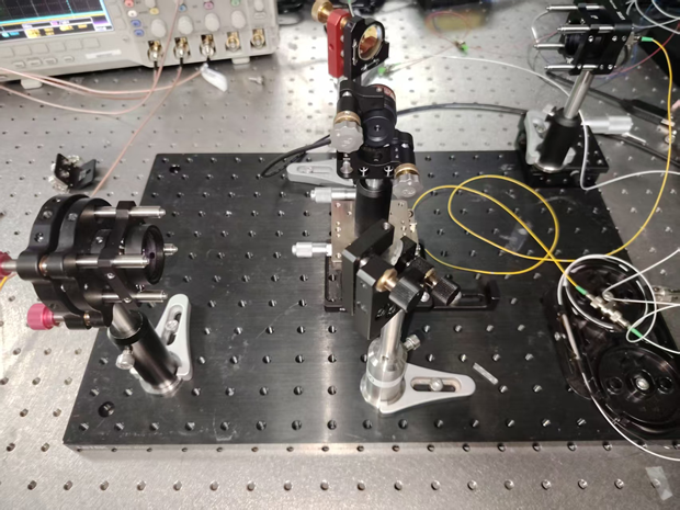
Figure 3. Physical apparatus of the optical cavity experimental platform
In the control subsystem, the hold logic and the gate controller block were both generated by Moku GenInst Studio and deployed alongside the Moku Laser Lock Box. These custom modules provide the synchronous trigger signal, simultaneously controlling the optical switch state and the frequency track and hold modes to guarantee strict synchronization between optical routing and feedback control.
To isolate and verify the efficacy of the controller hold strategy, the reference laser was operated continuously during the test, while only the electronic error signal input to the frequency-locking controller was gated. This allows direct evaluation of the controller’s ability to maintain cavity stability in hold mode without altering optical paths.
During the hold window, a photodetector monitors the cavity transmission signal to analyze frequency drift. If transmission remains near the resonance peak throughout the hold period, it confirms that the frozen voltage adequately preserves cavity lock.
Figure 4 presents the time-domain waveforms acquired by the Moku Laser Lock Box, characterizing the dynamic response of the cavity during triggered control suspension in the lock-hold experiment. The top trace shows cavity transmission, the middle trace is the trigger signal, and the bottom trace depicts the corresponding feedback control signal.
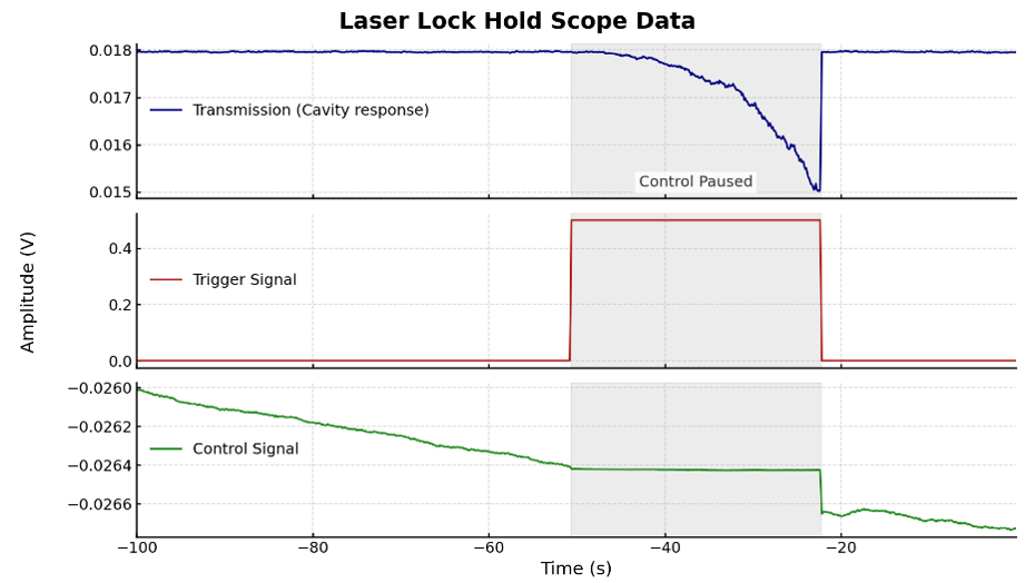
Figure 4. Oscilloscope time-domain waveforms of the cavity dynamic response during laser lock-hold testing. Top: cavity transmission; middle: trigger signal; bottom: feedback control signal.
When the trigger signal transitions high and feedback control is suspended, the cavity does not immediately experience significant drift. During the initial seconds of the hold phase, transmission remains stable, demonstrating that the cavity can maintain near-resonance conditions solely based on the frozen feedback output. As the hold duration extends further, uncompensated disturbances such as mechanical vibrations and thermal drift accumulate, causing the cavity to gradually deviate from resonance and the transmitted intensity to decline.
When the trigger signal returns low, the feedback control loop immediately resumes active control, adjusting the actuator to compensate for accumulated cavity drift and realigning the resonance with the laser wavelength. Transmitted power rapidly recovers to its initial high level, verifying that feedback locking reliably restores resonance.
The experimental results demonstrate that the interleaved stabilization architecture using the Moku Laser Lock Box successfully resolves the fundamental conflict between continuous optical cavity locking and low-noise single-photon detection. By synchronizing optical gating with the controller’s track-and-hold states, the system provides a dark measurement window while preserving the long-term resonance stability of the filtering cavity.
Without optical hardware changes, this approach is applicable to cascaded filtering and quantum conversion systems, providing a clear experimental reference for using Moku to verify the feasibility of such interleaved control schemes in quantum network applications.
Acknowledgements
We would like to express our gratitude to Prof. Chang-Ling Zou and Jiahua Zou from his group at the University of Science and Technology of China for generously providing the optical system and performing the experimental validations. Jiahua Zou noted that the Moku all-digital signal processing platform provided robust and effective support for the laser lock-hold experiments, enabling stable and reliable interleaved locking control. Furthermore, he highlighted that the Generative Instrument (GenInst) capability provided by Liquid Instruments, by directly compiling deployable FPGA bitstreams from natural language prompts, substantially accelerated custom feature development and reduced reliance on traditional FPGA hardware description languages.
References
[1] Werner, T., et al. “Electro-optic conversion of itinerant Fock states.” arXiv preprint arXiv:2602.00928 (2026). https://arxiv.org/abs/2602.00928
[2] Chen, L., et al. “Low-noise Optomechanical Single Phonon-photon Conversion for Quantum Networks.” Nature Communications 17, 1187 (2026). https://doi.org/10.1038/s41467-025-67956-2