






Introduction and challenge
Microelectromechanical systems (MEMS) harness the electrical and mechanical properties of silicon to integrate both mechanical and electronic structures for detecting acceleration, rotation, angular speed, and more. The core component of a MEMS device comprises a mass suspended perpendicular to the MEMS device’s motion, resonating within its frame in the driving direction. The Coriolis acceleration induced by the rotational movements can be sensed by measuring the frame’s movements in the sensing direction.
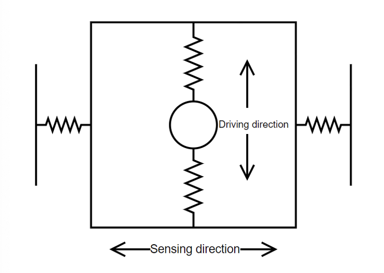
MEMS devices typically exhibit device-to-device variations, which can pose challenges in their characterization and measuring the rotation accurately. Characterizing these devices and performing measurements in-house requires a variety of instruments to complete the process. For example, a Frequency Response Analyzer for resonance identification, a phase-locked loop (PLL) for resonance tracking, a PID controller for amplitude stabilization, and a Lock-in Amplifier for measuring the device’s response to movements. In this example, researchers at Southeast University China used three independent Lock-in Amplifiers and a PID Controller, all within Moku:Pro, to both track the performance of their MEMS device and stabilize it. Moku:Pro offers a comprehensive, integrated solution with low noise inputs for systematic MEMS control and characterization. It utilizes four independent instrument slots in Multi-Instrument Mode and over 14 test instruments, encompassing all the necessary instruments mentioned above, along with additional powerful instruments like the Laser Lock Box for laser frequency stabilization and the Phasemeter for precise phase-sensitive measurements.
System diagram
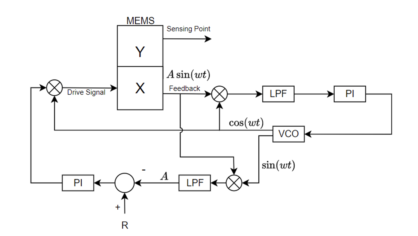
To accurately track and stabilize the MEMS device, researchers first divide it into two parts: the drive mode (X) and the sensing mode (Y). These two parts are the feedback-stabilized drive signal path and signal detection path, respectively. The X part has a stimulus signal input (Drive signal) and a feedback signal output (Feedback). The stimulus signal is responsible for driving the device at its resonant frequency and stabilizing the amplitude of its output signal. To ensure proper function, the device requires an external excitation signal since it lacks internal spontaneous driving mechanics. The deviation between the Drive signal’s frequency and the resonator frequency can be monitored by examining the phase difference between the Drive and Feedback signals. Given that the phase response of the MEMS device is monotonic over the driving frequency, it attains a 90° phase shift only when the driving frequency coincides precisely with the resonator frequency. This process underscores the need for a comprehensive feedback loop within the system. This loop regulates the drive signal’s frequency to maintain a 90° phase difference between the drive and feedback signals, thereby stabilizing it at the resonant frequency. The closed-loop control system, comprising a mixer, low-pass filter, proportional-integral (PI) controller, and voltage-controlled oscillator (VCO), is already incorporated as a PLL module. This integrated system is present in various Moku instruments such as the Lock-in Amplifier, Laser Lock Box, and Phasemeter. To ensure resonance stability, it is necessary to implement feedback signal amplitude stabilization, compensating for system noise and temperature variations. We first set the target input signal amplitude 𝑅, then a Lock-in Amplifier measures the output signal’s amplitude as seen in Figure 2. The difference between the measured amplitude and 𝑅 becomes the error signal for the feedback PI controller, adjusting the drive signal amplitude to stabilize the device’s output.
Experiment
In this experiment, Figure 3 illustrates the connections between Moku:Pro and the MEMS device. The X input and output of the MEMS device are linked respectively to Output 1 and Input 1 of Moku:Pro, establishing the Feedback-Drive control path. The Lock-in Amplifier in Slot 2 calculates the Feedback signal’s amplitude A in real time. This amplitude A is then sent to the PID Controller in Slot 3 for generating an amplitude control signal. Given the inherent 90° phase difference between the input and output of the X path, we configure another phase-locked loop (PLL_2) to introduce a 90° phase shift to the sin(ωt) signal from PLL_1, resulting in a cos(ωt) signal with a unity amplitude. Subsequently, the mixer of the second Lock-in Amplifier in Slot 4 amplitude modulates cos(ωt) with the control signal from the PID Controller to control the Drive signal’s amplitude for mass resonating amplitude stabilization. Multi-Instrument Mode on Moku:Pro is configured according to the design depicted in Figure 3, with the Moku: app configuration interface screenshot shown in Figure 4. The signal paths between adjacent slots and signal buses are digital, ensuring optimal signal quality while minimizing delay and supplying no additive noise. Analog inputs are labeled as In 1 to 4, and analog outputs are labeled as Out 1 to 4.
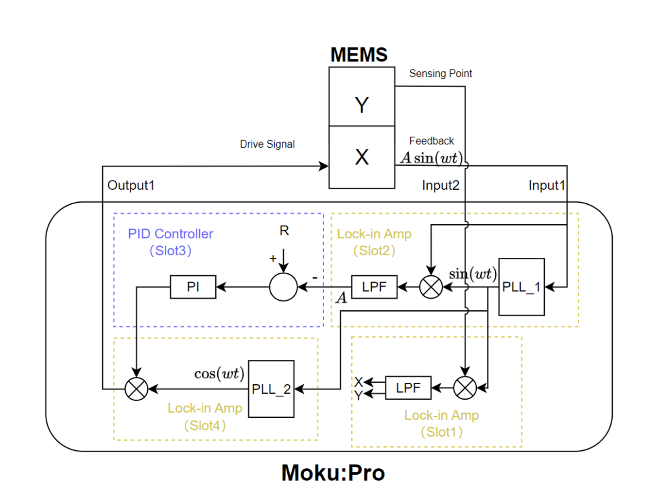
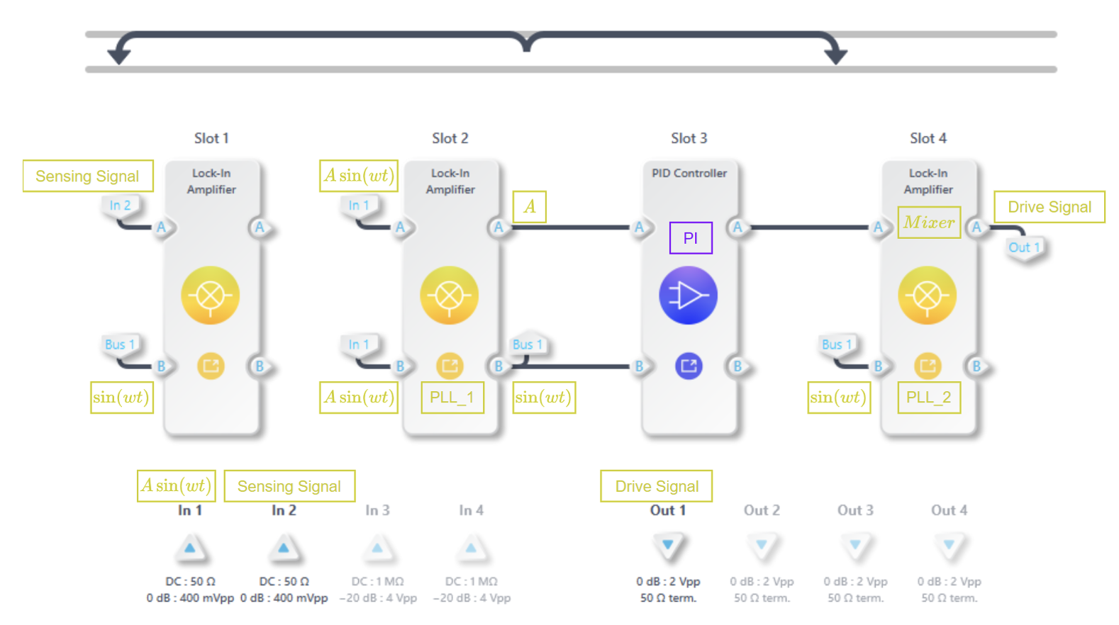
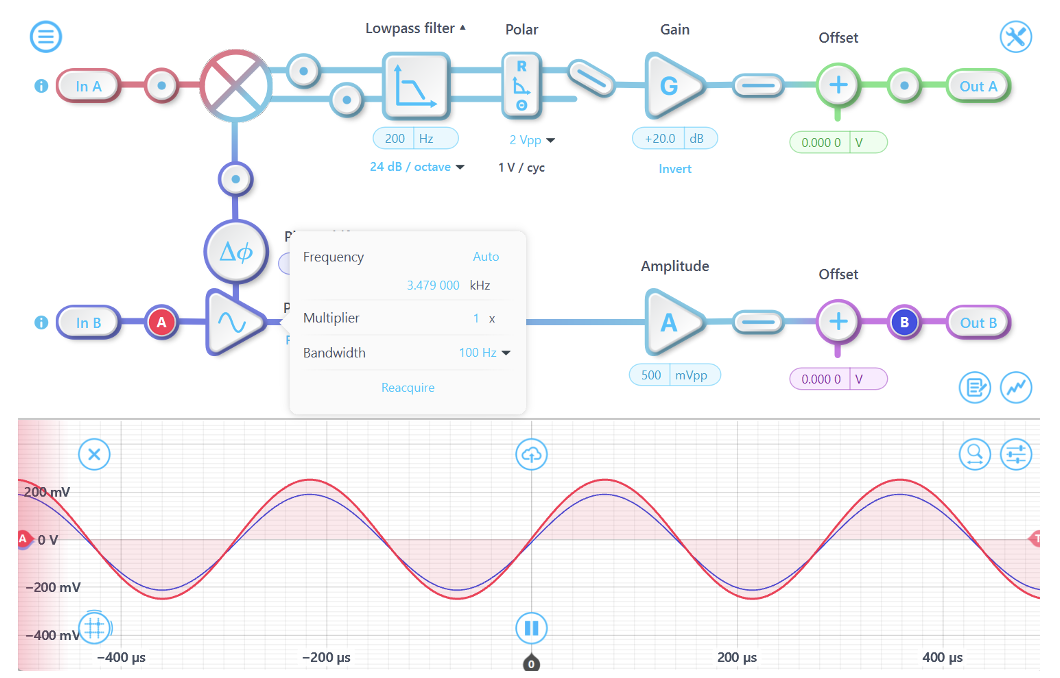
Figure 5 describes how the Lock-in Amplifier in slot 2 is set up, with polar coordinate transformation and the PLL enabled. The PLL is set to start at a frequency of 3.479 kHz and has a tracking bandwidth of 100 Hz. The In B and Out B signals are synchronized, which indicates that the PLL is tracking the MEMS resonance correctly. We configure the lowpass filter within the Lock-in Amplifier at 200 Hz with a slope of 24 dB/octave, filtering out the high-frequency components, or the sin(2ωt) signal, from the mixer’s output. Following this filtering process, the signal undergoes polar coordinate transformation, with its amplitude A serving as the input for the PID Controller to perform mass resonating amplitude stabilization control.
In Figure 6, we configure the PID Controller in Slot 3 as a PI controller aimed at minimizing the difference between the Feedback signal’s amplitude A and the target value. Using the input control matrix, we can invert the sign of the In A signal, then designate the target value as 100.4 mV on the Input offset, making the input of the Controller module the amplitude error signal. We then set the Integrator crossover frequency to 3.125 Hz and the Proportional gain to -24 dB to ensure low-bandwidth control for the temperature drifts. The Output offset is configured as 200 mV to maintain a fixed initial amplitude value before engaging the PID Controller. As observed, the amplitude A is stabilized at 100.4 mV.
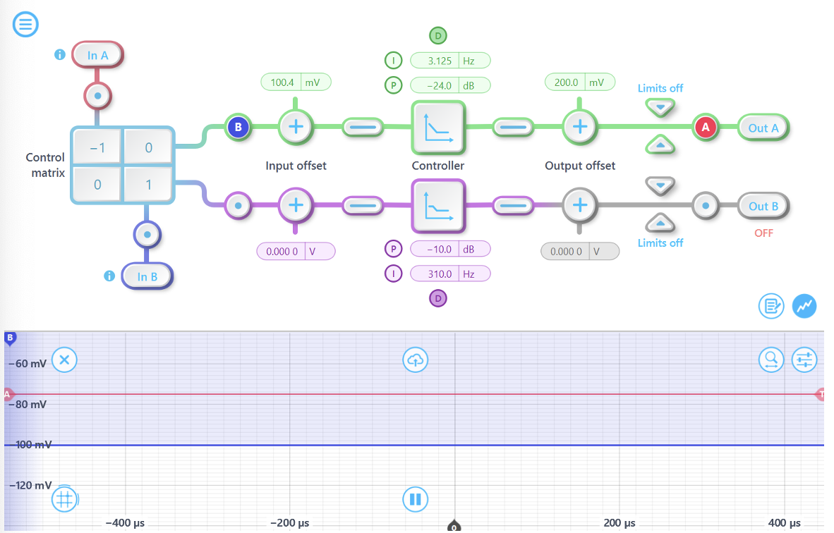
Figure 7 depicts the configuration of the Lock-in Amplifier in Slot 4. The PLL in this Lock-in Amplifier is set up with the same initial frequency and tracking bandwidth as the one in Slot 2. However, we apply a 90° phase shift to the PLL in Slot 4 to achieve phase offset compensation between the Drive signal and Feedback signal. In A in Figure 7 represents the amplitude control signal from the PID Controller, and this control signal changes the amplitude of the PLL output signal cos(ωt). A lowpass filter with a corner frequency of 5 kHz allows the passage of cos(ωt), and the Out A is connected to the X signal path to output the in-phase component. Out A is then connected to Moku:Pro analog Out 1 port, which links to the MEMS Drive signal input port.
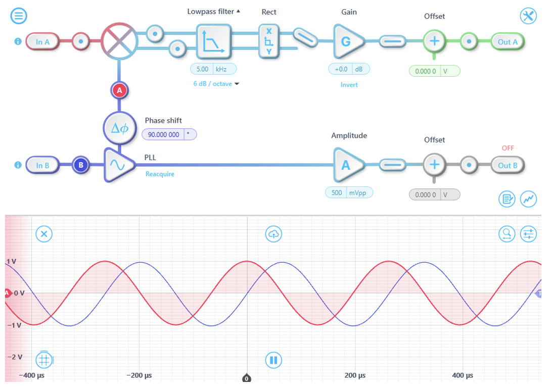
At this step, Moku:Pro successfully drives and stabilizes the MEMS device, tracking the signal displayed on Probe A (red) at the resonant frequency of 3.480 kHz, closely matching the expected resonant frequency of 3.479 kHz. Additionally, the 90° phase difference between the input Feedback signal and the output Drive signal of the device is also accurately detected.
Summary
In this experiment, Moku:Pro demonstrated strong real-time signal processing capabilities and high flexibility. Moku:Pro used Multi-Instrument Mode to drive the device and provide a stable lock at the MEMs device resonant frequency with three Lock-in Amplifier instruments and one PID Controller, all deployed simultaneously through a single FPGA-based device. The Lock-in Amplifier in Multi-Instrument Mode conducted measurements on the device, providing a complete reflection of the device’s output response to rotational stimuli. Overall, this validated the feasibility of Moku:Pro as a solution for MEMS measurement and control. By configuring Moku:Pro, it was possible to achieve complete drive of the device and measurement of open-loop signals. Combined with an external hardware mixer or an additional Moku:Go as a multiplier, Moku:Pro also had the potential to accomplish the force-to-rebalance closed loop on the sensing axis. Compared to similar instruments in the market, Moku:Pro not only demonstrated its excellent hardware qualities but also provided a systematic solution relying on its high flexibility. We would like to thank Prof. Xukai Ding for providing the MEMS device and coordinating the testing.
Questions?
Get answers to FAQs in our Knowledge Base
If you have a question about a device feature or instrument function, check out our extensive Knowledge Base to find the answers you’re looking for. You can also quickly see popular articles and refine your search by product or topic.
Join our User Forum to stay connected
Want to request a new feature? Have a support tip to share? From use case examples to new feature announcements and more, the User Forum is your one-stop shop for product updates, as well as connection to Liquid Instruments and our global user community.