Please update your browser. For the best Liquid Instruments experience, update to the latest version of Chrome, Edge, Firefox, or Safari. Update Microsoft Edge.
Liquid Instruments Logo
Products
Hardware Platforms
Moku:Delta
Moku:Delta
New
For advanced design and validation
Moku:Pro
Moku:ProFor versatile test and measurement
Moku:Lab
Moku:LabFor experimental research labs
Moku:Go
Moku:GoFor quick testing and debugging
Compare Hardware
Compare HardwareView a side-by-side of all Moku hardware
Technologies
GenInst Studio
New
Generate personalized instruments
Integrated InstrumentsProfessional-grade instruments at your fingertips
Neural NetworkFPGA-powered neural network integration
Multi-Instrument ModeCombine instruments to create a customized test system
Moku CompileCode, compile, and deploy to your Moku's FPGA
Software
MokuOSDownload the Moku app for Windows, macOS, iPadOS & visionOS
APIsPython, MATLAB, LabVIEW
UtilitiesCommand line and graphical tools for file conversion
Instruments
Analysis
Oscilloscope
Spectrum Analyzer
Frequency Response Analyzer
Lock-in Amplifier
Phasemeter
Logic Analyzer / Pattern Generator
Time & Frequency Analyzer
Data Logger
Generation
Waveform Generator
Arbitrary Waveform Generator
Control & Conditioning
PID Controller
Digital Filter Box
FIR Filter Builder
Laser Lock Box
Custom & Utility
GenInst Studio
New
Gigabit Streamer
Custom Instrument
Neural Network
Multi-Instrument Mode
Applications
Optics and Photonics
Microscopy and Spectroscopy
Photon Counting
Quantum Optics
Aerospace and defense
A&D Instrumentation
Component Test
Automated Testing
Semiconductor Test
Control Systems and Bode Analysis
MEMS Testing
AI and Machine Learning
Generative Instrumentation
New
Neural Networks
Education
Education and Research
Resources
App Notes
Blog
Case Studies
Coursework
Guides
Product Documentation
Publications
Webinars
White Papers
Support
Company
Contact Us
About Us
Leadership
Partners
News & Updates
Press
Events Calendar
Careers
Store
Moku:Delta
Moku:Pro
Moku:Go
Upgrade Moku:Pro
Upgrade Moku:Lab
Upgrade Moku:Go
0
Get a quote Buy Now
Build personalized instruments with GenInst Studio in minutes, not months. | Register for the webinar
Case studies • November 8, 2019

PDH technique with the Moku:Lab Laser Lock Box

An FPGA-based, all-in-one solution for laser frequency locking


    In this application note, we cover the real-world story of how one of our customers replaced several sophisticated electronic devices with Moku:Lab and used the Pound-Drever-Hall (PDH) technique to lock an Innolight Prometheus laser to a cavity.

    Download user manual
     

    Learn more about our ebook: The ultimate guide to PDH locking


    Introduction to the PDH technique

    The Pound-Drever-Hall (PDH) technique was first introduced by R.V. Pound, Ronald Drever, and John L. Hall in 19831. It is a widely used method to match the emitting optical frequency of a laser to a Fabry-Perot cavity. When laser light is directed into a cavity it is reflected, transmitted, or absorbed. The closer the length of the cavity is to a precise number of half wavelengths of the laser, the more of the laser’s energy is transmitted. Unfortunately, both the frequency of the laser and the length of the cavity vary continuously depending on a range of factors like ambient temperature, injection current, and quantum fluctuations. PDH locking uses light reflected from the cavity to create an error signal that can be used to make small changes in either the length of the cavity or the frequency of the laser so that they remain matched and transmission is maximized.

    The PDH technique uses a photodetector to capture the reflected light, which has been modulated by an electro-optical modulator (EOM) and mixes this signal with a local oscillator before passing it through a low-pass filter to separate the component of the signal which provides an unambiguous indication of not only how far the system is from resonance but in which direction adjustments must be made to restore resonance. The readout signal is then sent into proportional-integral-derivative (PID) controllers to create an error signal. Details about the theory of the PDH technique can be found in a few review papers and dissertations. To perform PDH locking, several dedicated and custom-made electronic instruments are required including signal generators, mixers, and low pass filters. The Moku:Lab Laser Lock Box integrates most of the PDH electronics into a single, compact, easy-to-use instrument that provides high precision laser frequency locking.


    Experimental setup

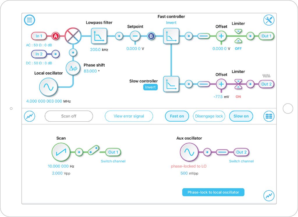
    The Moku:Lab Laser Lock Box integrates the Waveform Generator, mixer, low-pass filter, and two cascaded PID controllers that are used for the PDH technique. By adjusting the laser cavity’s length, it can monitor the amplitude of the reflected light and display the PDH signal in real-time on the screen. The users can lock the laser to any zero-crossing point with a single tap.

    Figure 1: Main user interface of the Moku:Lab Laser Lock Box

    Figure 1: Main user interface of the Moku:Lab Laser Lock Box

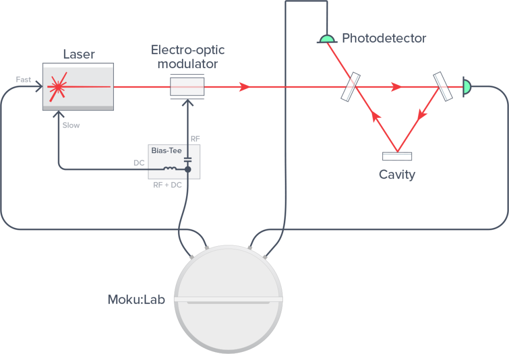
    In an example setup, a Prometheus laser (Innolight, 20NE) was modulated by an electro-optical modulator (EOM, iXBlue, NIR-MPX-LN-0.1) and redirected into a three-mirror traveling wave cavity (168 mm, i.e. an FSR of 1.78 GHz) with a linewidth of 190 kHz. The reflected light was captured from the prompt reflection of the input coupler. Two photodiodes (PD, Thorlabs, PDA05CF2) were placed to detect the transmitted and reflected light from the cavity. The signals detected on the PDs were fed into Moku:Lab input 1 (mixer input, AC coupled @ 50 Ω) and 2 (monitor, DC coupled @ 50 Ω). A local oscillator (LO) signal of 500 mVpp at 3.0 MHz was generated with the Moku Laser Lock Box waveform generator. The LO was then sent from Moku output 2 to drive the EOM via a biased Tee (Minicircuits, ZFBT-6G+).

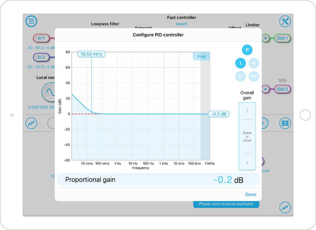
    A digital copy of the LO waveform was also used to demodulate the reflected response from the optical cavity using a digitally implemented mixer followed by a digital 4th-order Butterworth low pass filter with a corner frequency of 300.0 kHz. The phase shift of the LO at the mixer was adjusted by scanning the laser frequency across the cavity resonance and adjusting phase delay until the error signal peak-to-peak voltage (slope) was maximized. The fast PID controller was configured with an integrator unity gain frequency (0 dB point) of 5.8 kHz with an initial integrator saturation corner of 100 Hz. The output 1 of the fast PID was then connected directly to the laser’s piezo to actuate laser frequency. In the scan mode, the ramp signal was also generated from this output to discover the cavity resonances. The slow PID controller was configured to have proportional gain of -32.2 dB with an integrator crossover frequency of 200 mHz. This low-frequency PID controller output was then separated using the Bias-Tee at output 2 and sent into the temperature control BNC of the laser. A 20 dB attenuation (Minicircuits, HAT-20+) was also placed in-line to this laser temperature actuator to reduce its sensitivity.

    Figure 2: Experimental setup of PDH technique with Moku:Lab

    Figure 2: Experimental setup of PDH technique with Moku:Lab


    Employ PDH technique laser frequency locking with Moku:Lab

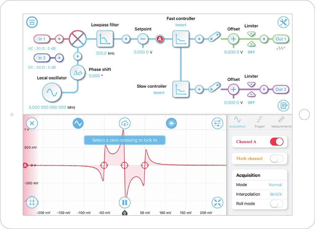
    To engage the PDH lock, the PDH readout signal was first generated by a ramp scan in laser lock mode. The slow temperature offset was adjusted to bring the cavity resonance close to the middle of the scanning range. The zero-crossing point in the middle was then selected as the locking point using a single tap. This engaged the fast PID controllers and the laser frequency was locked to the cavity. The integrator saturation was then switched off to bring the laser frequency to the DC frequency of the cavity. The slow controller was then engaged, this offloads control work from the laser’s piezoelectric transducer (PZT) at frequencies below 0.1 Hz and ensures the laser remains locked over wide variations in room/lab conditions.

    Figure 3: Example PDH error signal plot and tap to lock zero-crossing points

    Figure 3: Example PDH error signal plot and tap to lock zero-crossing points

    Figure 4: Example configurations of slow (temperature) PID controller

    Figure 4: Example configurations of slow (temperature) PID controller


    Results and discussion

    Locking of the laser to the cavity to the TEM00 mode was verified by monitoring the transmitted photodetector power and viewing the laser mode shape on transmission with a CCD camera (one could also use an infrared-sensitive viewing card). Time domain signals of these monitor signals were easily viewed live in the Moku:Lab Laser Lock Box built in oscilloscope.

    Basic optimization of the overall loop gain was made by using the built-in oscilloscope measurement feature to compute the error signal RMS. The gain was increased to minimize the RMS of the error signal; too much gain caused oscillations, and too little gain meant that laser frequency perturbations remained insufficiently suppressed. Further loop performance improvements can be made with frequency domain optimization. This can be done by injecting a swept sine disturbance between the Moku:Lab output 1 and laser piezo using a summing pre-amplifier and measuring the suppression of this injected perturbation within the loop. Such a measurement can be carried out using a second Moku:Lab using its Frequency Response Analyzer instrument. In these highly optimized configurations, the unity gain frequency of the loop should be optimized to 30-60 kHz (higher than this will often be too fast for the laser’s piezo to respond).

    In one test the control loop performance was verified using a one-cavity-two-lasers test. A second laser was locked to the cavity one Free Spectral Range (FSR) above the first laser’s lock with a second identical Moku:Lab Laser Lock Box setup. With a lock at two independent frequencies, the two lasers were compared with identical common cavity noise but independent electronic and Moku digitization noise. The residual frequency variation between these two locked lasers was independent of cavity spacer noise, thermal noise of the cavity coatings, and common vibrations from the laboratory environment. This noise, due only to the control loop and sensors, was measured by combining light from both laser paths into a high-speed photodetector, mixing it down with a stable GHz function generator, and using a third Moku:Lab instrument, a Phasemeter, to track the frequency deviations. The Moku:Lab Phasemeter has been used to read out the residual frequency noise by generating an ASD of the relative frequency noise. Residual noise due to the control loop was found to be 0.1 Hz/√Hz at 10 Hz per loop. The actual absolute performance of the cavity laser lock will ultimately be limited at low frequency by fundamental thermal coating noise.


    Acknowledgment

    We would like to thank Andrew Wade, Kirk McKenzie, and The Australian National University for providing us the details of their experiment, explanation of the use of Moku:Lab and feedback. The experiment at the ANU was supported by the ARC Centre of Excellence for Gravitational Wave Discovery.


    References

    [1] Drever, R. W. P., Hall, J. L., Kowalski, F. V., Hough, J., Ford, G. M., Munley, A. J., & Ward, H. (1983). Laser phase and frequency stabilization using an optical resonator. Applied Physics B, 31(2), 97-105.

    [2] Nickerson, M. A review of Pound Drever Hall laser frequency locking. JILA, University of Colorado and Nist.

    [3] Lally, E. M. (2006). A narrow-linewidth laser at 1550 nm using the Pound-Drever-Hall stabilization technique (Doctoral dissertation, Virginia Tech).


    Have questions or comments?

    Contact us

    Try Moku in demo mode Download the Moku app → Get answers to FAQs Visit Knowledge Base → Connect with Moku users Join the user forum →

    Other Recommended Case studies

    Case studies
    Phase Stabilization for Quantum Key Distribution with Moku:Pro

    Learn how researchers at the University of Hamburg are using Moku to improve signal fidelity for continuous-variable QKD.

    Featuring: Moku:Pro, PID Controller, Lock-in Amplifier, Laser Lock Box

    Date: Mar 16, 2026

    Case studies
    Enabling Dual-Wavelength Nanosecond Fiber Lasers for Multi-Contrast Photoacoustic Imaging with Moku:Pro

    Learn how researchers at the University of Hong Kong used Moku:Pro to generate synchronized shortwave-infrared nanosecond pulses and stabilize modulation depth for dual-wavelength photoacoustic imaging.

    Featuring: Moku:Pro, Waveform Generator, PID Controller

    Date: Dec-19-2025

    Case studies
    Teaching lock-in detection with Moku:Go

    Learn how students at IIT Madras are gaining hands-on experience in using the Lock-in Amplifier instrument on Moku:Go

    Featuring: Moku:Go, Lock-in Amplifier

    Date: Dec-15-2025

    Back to all Case studies

    Nav

    • Products
    • Instruments
    • Resources
    • Support
    • Company
    • Contact Us
    • Privacy Policy
    • Terms of Use

    Offices

    United States
    (619) 332-6230
    12526 High Bluff Dr.
    Suite 150
    San Diego, CA 92130

    Australia
    +61 2 6171 9730
    243 Northbourne Avenue
    Suite 1, Level 1
    Lyneham, ACT 2602

    Australia
    +61 3 7073 3594
    Suite 5C, Level 5,
    700 Swanston Street,
    Carlton, VIC – 3058


    Follow us

    LinkedIn YouTube X Facebook Instagram

    官方微信

    © 2026 Liquid Instruments. All rights reserved.