






One method for determining the distance to an unknown object involves reflecting pulses of light off the object and detecting the reflection. The time difference between the transmitted and received pulses is then calculated and multiplied by the speed of light, giving the total distance that the light traveled back and forth from the object. This method, called a time-of-flight measurement, is often used in radar and LiDAR applications. In this application note, we use Moku:Go, an FPGA-based device from Liquid Instruments that offers a reconfigurable suite of test and measurement instruments, in conjunction with a commercial range finder to perform precise time-of-flight measurements. The range finder will emit and detect infrared pulses and provide a stream of serial data to the Moku:Go device. Moku:Go also serves as the power source and the decoder for the serial data provided by the range sensor. We will demonstrate how to visualize this serial data using both the Moku Oscilloscope and Logic Analyzer / Pattern Generator instruments. Finally, we will automate the measurement using the Moku Python API.
Required materials
To perform this experiment, you will need the equipment listed below. See Figure 1 for a visual guide. Moku:Go: This setup specifically calls for a Moku:Go device because it offers a built-in programmable power supply. Here, we use it to power the LiDAR distance sensor. If you have different Moku hardware, then you will also need a 5V DC power supply. Two banana-plug-to-alligator-clip wires: These will connect to the Moku:Go and provide 5 V of DC power to the range finder. One BNC-to-alligator clip wire: This will be used for passing the serial data from the range finder to the input of the Moku:Go. LiDAR distance sensor: The range finder that we are using for this experiment is the TF Luna from Benewake. The TF Luna measures distance by calculating the time-of-flight of a pulse train of infrared light. This data is then sent to the receiver via UART serial encoding. A link to the documentation for this device is available in the References section at the end of the article. The TF Luna has six connecting wires; here, we use only the power, ground, and Tx wires. These connections are labeled in Figure 1.
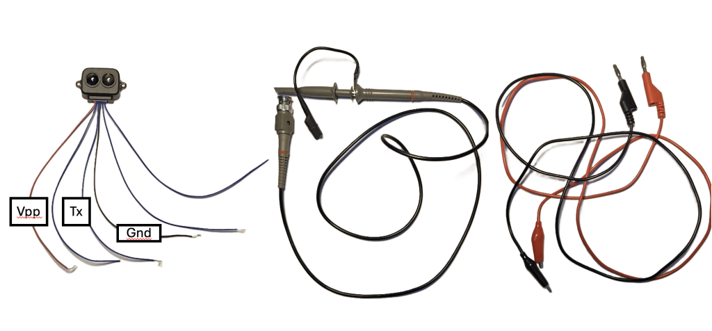
Figure 1: Equipment required for the time-of-flight demo. Left: TF Luna, with the three connections labeled. Center: BNC-to-alligator connection wire. Right: Banana plug-to-alligator clip connection wires.
Setting up the equipment
These steps outline all of the connections to be made between the instruments. The full schematic is shown in Figure 2.
- Prepare the LiDAR range sensor. With the TF Luna, you will need to remove one end of the connector, and then use wire strippers to expose a section where the alligator clips can connect. If you are using a different sensor, make sure you have its documentation on hand when following the subsequent steps.
- Connect the range sensor to the power supply. Attach an alligator clip to the Vpp wire (red), and insert the banana plug into Power 1 on the back side of Moku:Go.Repeat with the next wire, fixing the clip to the GND wire (black) and connecting the banana plug into the shared ground between Power 1 and Power 2.
- Connect the data transmission cable. Plug the BNC end of the data transmission cable into Input 1 on Moku:Go. Connect the red alligator clip (or probe, depending on your cable) to the Tx wire on the range sensor. If there is also a grounding clip on the cable, you can fix it to the GND pin on the range sensor, so that it and the power supply share a common ground.
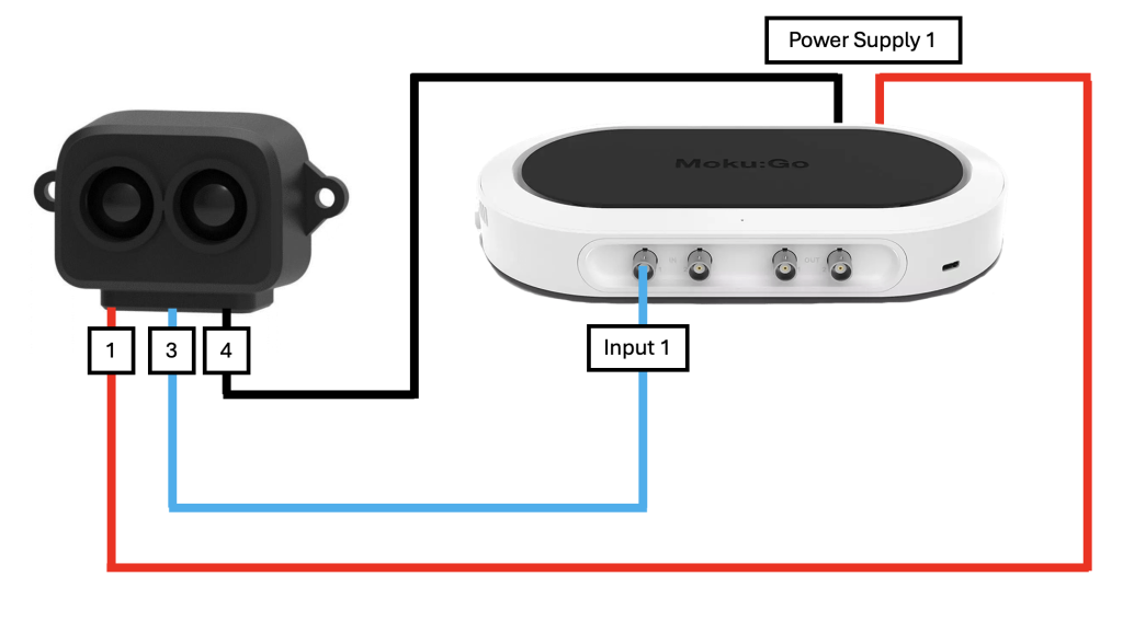
Figure 2: Connections between the range sensor and Moku:Go. The device’s built-in power supply provides a 5 V power signal to the sensor. The Tx pin of the sensor provides serial data to Input 1 on Moku:Go.
Verifying and viewing the output
These steps will outline how to set up the Moku Oscilloscope to view the transmitted signal from the range sensor.
1. Launch the Moku Oscilloscope. From the main screen of the Moku software, click on the Oscilloscope to launch it in single-instrument mode. On the main Oscilloscope screen, there should be no signal on Channel A, as power has not yet been provided to the sensor.
2. Enable the power supply. On the Moku screen, click on the menu icon in the upper left corner (three parallel lines). Then click “Power Supply.” A new menu window will appear on-screen. Click the slider next to PPSU 1 to enable it, then change the voltage value to “5.000.” You should see the range sensor begin to draw current (~50 mA) from Moku:Go, as shown in Figure 3.
3. View the output on the Oscilloscope. Once power is enabled, return to the Oscilloscope screen. You should see a repeated pattern similar to the example shown in Figure 3. This is the serial data that is being transmitted by the range sensor, encoded in UART format. Each packet contains a number of bits of data, with the value of the bit determined by whether the voltage is high (3.3 V) or low (~200 mV). Having confirmed that the range sensor is functioning correctly, we will now use the Moku Logic Analyzer / Pattern Generator to interpret this serial data.
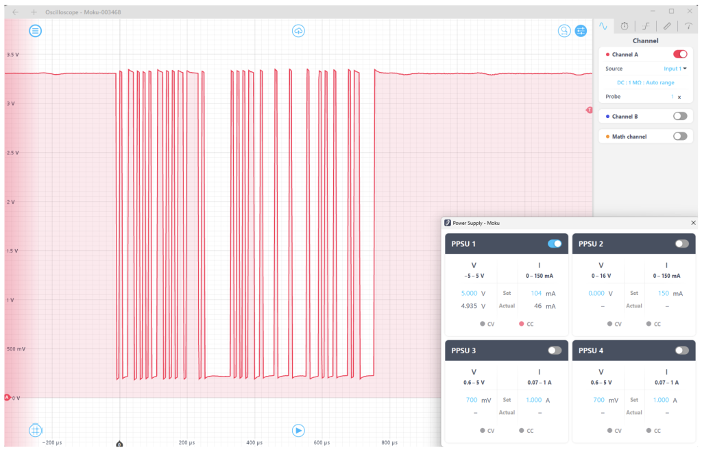
Figure 3: The Moku Oscilloscope and Power Supply, showing bursts of UART serial data.
Decoding the serial output
We will now set up the Moku Logic Analyzer / Pattern Generator to decode the UART serial data.
1. Launch the Moku Logic Analyzer / Pattern Generator From the main screen of the Moku software, click on Logic Analyzer / Pattern Generator to launch it in single-instrument mode. Since this reconfigures the Moku:Go FPGA, you must re-enable the device’s Power Supply to power the range sensor. To do so, follow the steps outlined in the section above.
2. Set up the acquisition. On the right-hand side of the screen, you will see the Acquisition menu. Change the source to “Analog inputs,” which will bypass the 16-bit digital I/O and use the analog inputs 1 and 2 as two-bit data. Since UART is a binary format, this is acceptable. Remove the Bit 1 display by clicking the “X” to the right of the plot. Under the “Timebase setting,” set the time span to 1.5 ms and the offset to -300 𝛍s. If the range sensor is powered on, you should see the serial pattern appear on the Bit 0 plot, as shown in Figure 4.
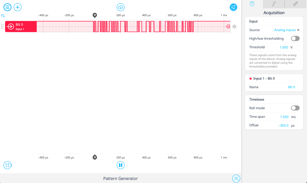
Figure 4: The Moku Logic Analyzer / Pattern Generator, showing a sequence of UART serial data, similar to the example shown in Figure 3.
3. Add the protocol decoder. The Moku Logic Analyzer / Pattern Generator can decode a number of standard protocols, including UART, which converts the serial data into hexadecimal format. To add a decoder, click the plus sign in the top left of the screen, as shown in Figure 5.
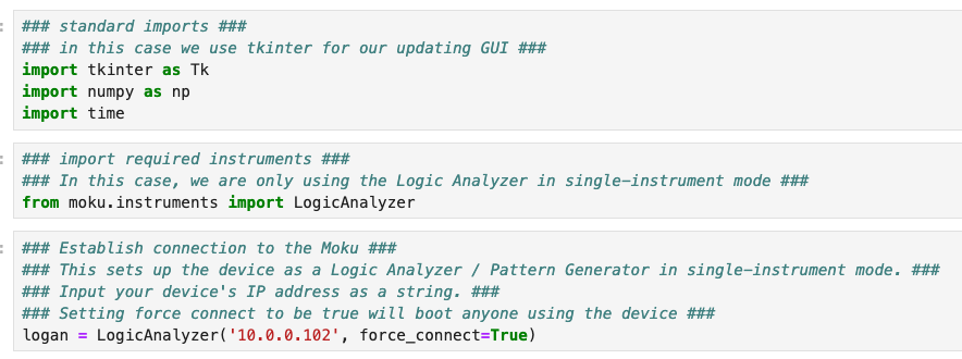
Figure 5: Adding the protocol decoder for the UART serial data.
4. Configure the protocol decoder. For the data to be properly decoded, the instrument must know how many bits of information are contained in the UART sequence, as well as the rate at which the information is arriving (also known as the Baud rate). This will depend on the exact nature of your range finder. If you are using the TF Luna, the configuration is shown in Figure 6. The data width is 8 bits with 1 stop bit, there is no parity check, and the default Baud rate is 115200. If the decoder settings match with those of the transmitter, you will see the hexadecimal numbers appear in the UART decoder line, as shown in Figure 6.
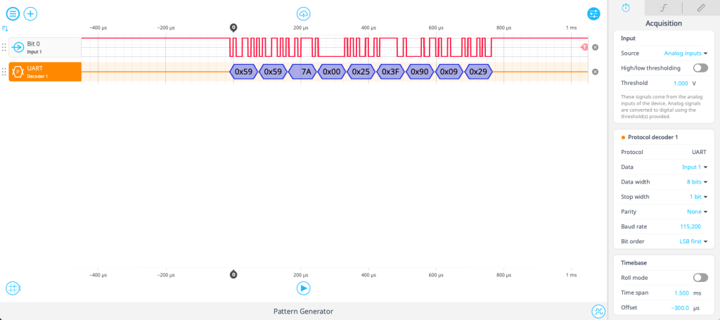
Figure 6: UART serial data converted to hexadecimal numbers.
7. Interpret the data. Refer to the documentation of your range sensor to make sense of the numerical data decoded by Moku:Go. In the case of the TF Luna, the default 9-byte data sequence is shown in Figure 7. The first two bytes are always 59, which is confirmed by the decoded data. Bytes 2 and 3 in this case provide the distance information in centimeters. If you put your hand over the range sensor, you can see this value change appropriately.
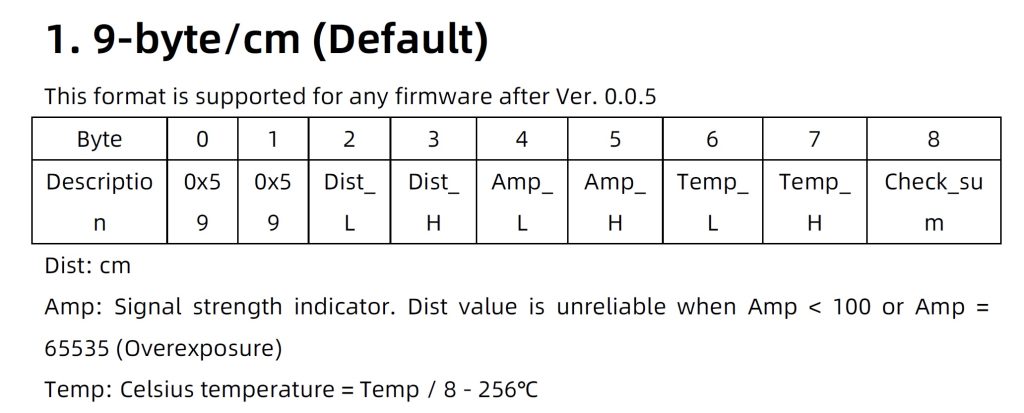
Figure 7: An excerpt from the TF Luna datasheet helps us interpret the results.
Automating the measurement with Python
Unfortunately, hexadecimal numbers are not intuitive for the perception of distance. In this section, we will use the Moku Python API to create an automated distance measurement tool that will continuously refresh the data. The following script is available from the Liquid Instruments Github page. A tutorial for setting up the Moku Python API is available here.
1. Import and connect. In addition to any “standard” imports that are needed, you must import any instruments you plan to deploy onto Moku:Go, as shown in Figure 8. In this example, we create an instance of the Moku Logic Analyzer / Pattern Generator and specify the device’s IP address.
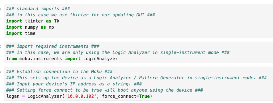
Figure 8: Import and connect the code.
2. Set up the power supply. Any function of Moku software can also be performed using the API, including the DC power supply. Specify your desired supply, as well as the maximum voltage and current values, as shown in Figure 9.
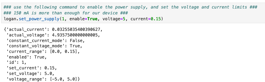
Figure 9: Set up the DC power supply.
3. Set up the Moku Logic Analyzer / Pattern Generator. This simply requires using a number of commands to provide the same information to the protocol decoder that we specified earlier, including the data width, stop width, Baud rate, and channel number. Note that “get_data” returns the entire trace of raw data, so we only ask it for the protocol analyzer data, labeled ‘pa1.’
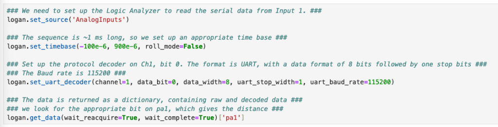
Figure 10: Set up the protocol decoder.
4. Display the data. Within the data array, we can see that the state variable alternates between “idle” and “data.” We want to look at the 3rd data bit, which corresponds to the 5th element in the array. Within this dictionary, we want the value attached to the ‘data’ key, which gives us our distance value in centimeters. After recovering this value, we use the tkinter package to create a display that updates with the most recent measured distance value. The code, along with an example window, is shown in Figure 11.
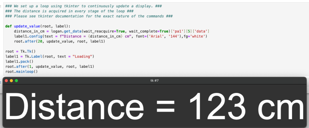
Figure 11: The code for a continuously updating display, along with the display itself.
Conclusion
Moku:Go is a powerful and flexible multi-tool for electronic test and measurement applications. In this demonstration, we used Moku:Go in conjunction with a range sensor to perform a time-of-flight distance measurement. Thanks to the flexibility of Moku:Go, we can power the sensor with the device’s programmable power supply, as well as view and decode the serial data using the Moku Oscilloscope and Logic Analyzer / Pattern Generator instruments. We also implemented a continuously updating range measurement script using the Moku Python API. To learn more about the Moku platform, click here. To explore the instruments cost-free, download our desktop app and select demo mode.
Questions?
Get answers to FAQs in our Knowledge Base
If you have a question about a device feature or instrument function, check out our extensive Knowledge Base to find the answers you’re looking for. You can also quickly see popular articles and refine your search by product or topic.
Join our User Forum to stay connected
Want to request a new feature? Have a support tip to share? From use case examples to new feature announcements and more, the User Forum is your one-stop shop for product updates, as well as connection to Liquid Instruments and our global user community.
References
Benewake TF Luna documentation: https://en.benewake.com/DataDownload/index_pid_20_lcid_21.html