






No single clock is perfect. Some oscillators have exceptional long-term stability, others shine in the short term, with vanishingly low phase noise over microsecond timescales. In fields from precision measurement to high-speed communications, performance depends on having the right kind of stability, and no single source can deliver it all. Moku:Delta solves this with a clock-blending architecture that fuses the strengths of multiple reference oscillators. A carefully engineered, nested PLL system assigns each clock the job it does best: narrow-band loops capture the superb long-term stability of high-quality references, while wider-band loops draw on the exceptional short-term performance of a VCXO. The result is low jitter across a wide range of time scales and onboard clock stability of ±1 ppb. For applications that demand integration into wider timing systems, Moku:Delta’s clock blending is extended to incorporate a 10/100 MHz external reference input, a 1 pps input, and a removable GNSS receiver.
Conventional jitter & phase noise control
Clock signal performance is typically characterized by the time jitter, the difference between a clock’s measured cycle and its ideal cycle. In the frequency domain, this jitter would translate to phase noise to represent the random frequency fluctuations of the oscillator. To reduce the amount of phase noise in an oscillator’s output, phase-locked loops are implemented to correct any unwanted variations. Voltage-controlled crystal oscillators (VCXO) are typically used to generate the output frequencies.
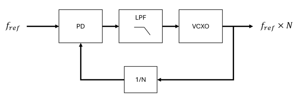
Figure 1: Typical PLL.
Figure 1 shows a typical PLL architecture with a reference oscillator at the input. The VCXO output is divided by N before being fed back to the phase detector (PD), allowing the PLL to multiply the reference frequency by N at the output. This type of PLL is referred to as a “jitter cleaner” because it tracks low-frequency variations in the “cleaner” reference oscillator within the loop bandwidth. The loop bandwidth is the frequency range over which the PLL responds to and corrects phase or frequency errors between the reference and the controlled oscillator. A narrow loop bandwidth means the PLL only corrects slow variations, while a wide loop bandwidth allows it to track faster changes. The loop band diagrams shown in figures 3 & 4 represent the frequencies at which the sources will determine phase noise. Below the loop bandwidth, the PLL follows the reference, passing low-offset noise to the output and suppressing the VCXO noise. Above the loop bandwidth, the reference noise is attenuated and the VCXO noise dominates the output. In other words, the loop filter acts as a low-pass filter for the reference noise and a high-pass filter for the VCXO noise. This creates a tradeoff of which noise source dominates the output. With a narrow loop bandwidth, more of the VCXO’s low noise dominates at higher offset frequencies, improving jitter performance, but the PLL is slower at tracking long-term reference drift. A wide loop bandwidth, on the other hand, allows the PLL to track the reference faster and suppress the VCXO noise further out, but it also passes more of the reference’s high-frequency noise to the output. The design goal is to balance the phase noise of the reference oscillator and the VCXO, along with the desired tracking speed of the PLL.
Moku:Delta nested PLL design (clock blending)
Moku:Delta has a multi-PLL architecture for optimal clock stability across all time scales. A 12.5 GHz VCO is used to generate the output, and it is driven by a 122.8 MHz VCXO locked to a 10 MHz oven-controlled crystal oscillator (OCXO) reference. To improve long-term stability, an additional PLL (Frequency Reference PLL), locked to an external oscillator, can be used to steer the VCXO PLL (Main). Even if the secondary reference oscillator has noisier short-term stability, it will not affect the overall short-term performance since, beyond the loop bandwidth, the low VCXO noise still dominates. This can be thought of as a hybrid reference oscillator, allocating loop bandwidths to the sources that have the least phase noise in those frequency bands.
Moku:Delta goes a step further and adds a third PLL (Synchronization Reference PLL) that disciplines the second PLL using a pulse per second (PPS) reference. A PPS signal provides highly accurate timing aligned to Coordinated Universal Time (UTC), but its individual pulses can exhibit short-term jitter due to environmental and satellite effects. If used with an extremely narrow loop bandwidth, the Synchronization Reference PLL corrects only ultra-long-term drift, leaving short- and mid-term noise performance dominated by cleaner oscillators.
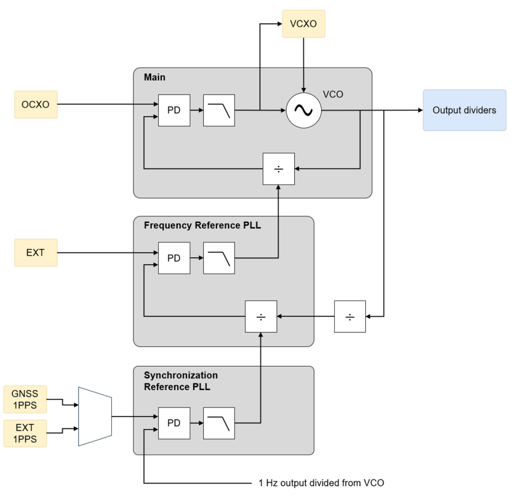
Figure 2: Moku:Delta clock-blending schematic. The main PLL (Main) driving the VCO output is steered by a second PLL (Frequency Reference PLL) locked to an external reference oscillator. The second PLL is steered by a third PLL (Synchronization Reference PLL) locked to a 1 Pulse Per Second (PPS) reference oscillator.
Figure 2 shows a schematic of the nested PLLs used in Moku:Delta’s clocking system. The main PLL (Main) is steered from a second PLL below it (Frequency Reference PLL). The second PLL is locked to an external 10 or 100 MHz reference oscillator. Enabling this reference removes any drift caused by the VCXO and OCXO oscillators, which is useful for synchronizing multiple devices to each other or to a more stable oscillator, such as an atomic clock. The second PLL is steered by a third PLL (Synchronization Reference PLL). The Synchronization Reference PLL is locked to a 1 pulse per second (PPS) reference, which can be externally applied through an SMA port, or directly from the Moku:Delta Global Navigation Satellite System (GNSS) module. The feedback is a 1 Hz output divided from the VCO, used for phase pull-in. This ensures that the synchronization reference not only stabilizes the frequency, but also provides an absolute phase reference–aligning all output clock edges with Coordinated Universal Time (UTC) markers. UTC is the international time standard used for clocks and communication systems worldwide. The GNSS provides precise timing signals by synchronizing to atomic clocks on satellites. The Moku:Delta GNSS module generates a 1 PPS signal for long-term time stability, with an accuracy of <5 ns. The GNSS reference also provides absolute timestamps aligned with UTC. Alternatively, the external 1 PPS reference does not have to use the GNSS module. Instead, a 1 PPS signal from an external GPS-disciplined oscillator or an atomic clock can be used to provide good long-term stability, but will not provide the absolute timestamps of the GNSS signal.
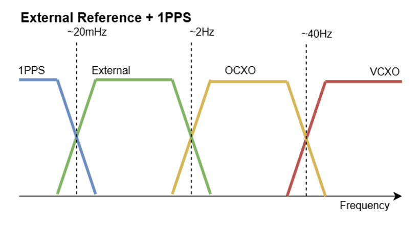
Figure 3: Blended clock loop bands.
Figure 3 shows the loop bands when all three PLLs are in use on the Moku:Delta. Above frequency offsets of 40 Hz (short-term stability), the phase noise of the VCXO dominates. Between 2 Hz and 40 Hz (mid-term stability), the OCXO dominates. The external reference dominates between 20 mHz and 2 Hz (long-term stability), and the 1 PPS source dominates for anything slower than 20 mHz (ultra-long-term stability).
What are the options for configuring the clock blending architecture?
The VCXO and OCXO will always be used for the clock generation signal on the Moku:Delta. The external reference and 1 PPS oscillators, however, are optional and can be enabled/disabled in the “Clock Blending Configuration” settings from the Main Menu (see Figure 4). Figure 5 shows how the loop bands are adjusted based on the different possible clock source configurations. The frequencies of the bands represent which frequencies each oscillator’s phase noise dominates. Users should choose their clock configuration based on their system’s timing needs. If the OCXO’s phase noise does not meet timing requirements, the external 10 or 100 MHz reference should be used if there is a low-jitter external reference available. If precise ultra-long-term timing is required, such as multiple day- or week-long measurements, the external 1 PPS or GNSS 1 PPS should be enabled. The GNSS 1 PPS should be used specifically if absolute timestamps are desired/necessary.
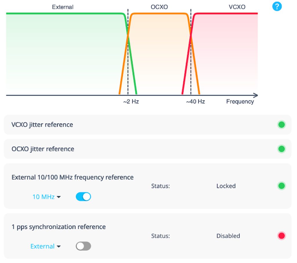
Figure 4: Clock blending configurations interface
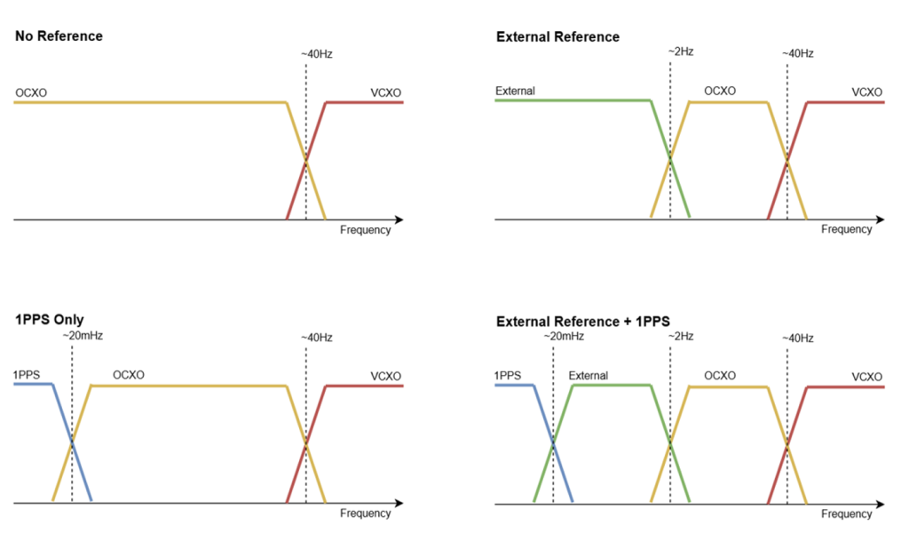
Figure 5: Different clock blending configurations on the Moku:Delta
Summary
Moku:Delta’s clock-blending architecture delivers extremely precise timing for test and measurement by leveraging the use of multiple reference oscillators optimized for different time scales. Users can tailor the clock configuration to their application by selecting which reference sources are enabled based on their timing needs. This flexible approach minimizes phase noise across all timescales, providing users with stable timing for both high-speed and long-duration measurements.