






This recap and Q+A complements our webinar: Achieving Precise Phase Control in Optical Applications with Digital Phase-locked Loops, which we co-hosted with Optica on February 22, 2024. If you weren’t able to attend live, you can register now for on-demand access. In addition to providing a webinar summary, we’re providing step-by-step instructions on how to implement the phase-locked loop (PLL) shown in the webinar and answering all audience questions below.
Webinar recap
The presentation consisted of three segments. In the first segment, we explained the concept of phase measurement, both by demodulation-free and lock-in methods. We examined the functions of a PLL, which results from the combination of a dual-phase lock-in detector and a voltage-controlled oscillator in a feedback loop. We also introduced the phasemeter, which uses a PLL and an integrator to provide precise, unwrapped phase information. In the second segment, we constructed an optical PLL with the fully digital Moku Lock-in Amplifier and Waveform Generator, deployed with our flagship Moku:Pro, a reconfigurable, FPGA-based device that offers a full suite of test instruments. We repeated the demo with the Moku Phasemeter, explored its functions, and discussed the advantages of both setups. In the final segment, we used the Moku Python API to re-implement the PLL in a Jupyter notebook, showing how each instrument can be called, configured, and measured within a single script.
Step-by-step PLL implementation instructions
Here’s how to use Moku instruments to replicate the PLL shown in the webinar. You can also find this information by downloading our PLL quick-start guide.
Step 1: Build your PLL system and set up connections
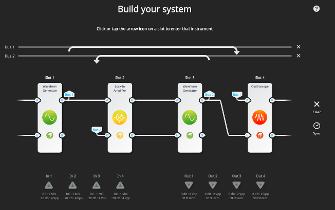
After selecting your Moku device, select Multi-instrument Mode to enter the “Build your system” screen. Set up a Waveform Generator in both Slot 1 and Slot 3, a Lock-in Amplifier in Slot 2, and an Oscilloscope in Slot 4. Make sure the connections follow the diagram below. Output A on Slot 1 should connect to both Slot 2, Input A and Slot 4, Input A. Slot 2, Output A should connect to Slot 3, Input A. Finally, Slot 3, Output A should connect to both Slot 4, Input B and Slot 2, Input B.
Step 2: Set up the input signal
Enter the Waveform Generator in Slot 1 and enable the output. Adjust the frequency and amplitude as needed. For the demo, we use 100 MHz and 1 Vpp.

Step 3: Enable the VCO
Open the configuration menu for the Waveform Generator in Slot 3. Enable the output and set the modulation type to frequency modulation (FM). Set the center frequency to 100.05 MHz (slightly offset from the input frequency) and the modulation depth to 50 kHz/V. Finally, change the source of the FM from “Internal” to “Input A.”

Step 4: Configure the Lock-in Amplifier and close the loop
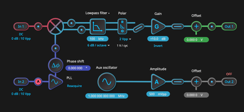
Enter the menu for the Lock-in Amplifier. In the upper right corner, click the settings icon and change the demodulation source from “Internal” to “External (PLL).” While not necessary for this demo, this is where you can also optionally enable PID control on the output. Change the lowpass filter to 100 kHz and make sure the Lock-in Amplifier is calculating polar coordinates. Click on the PLL block and select “Auto” for frequency and 100 kHz for bandwidth. Flip the switch to 𝜣 and give the signal a small gain boost — around 10 dB is sufficient. Make sure all the switches are closed and enable the output. Click “reacquire” near the PLL block.
Step 5: Verify your phase-locked loop
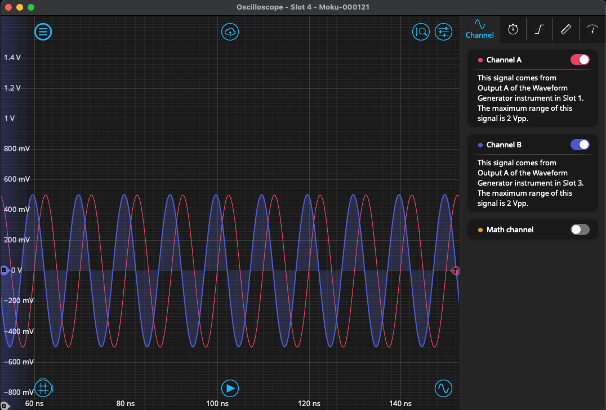
Enter the Oscilloscope and select an appropriate window from the “Timebase” tab, such as 100 ns. If both channels are enabled, you should see a phase-locked signal on both that should not drift or scroll in time. For verification, you can return to the Lock-in Amplifier screen to open and close the loop. The signal on Channel B should scroll past when the loop is open and lock back on to Channel A when it is closed again.
Questions from the audience, answered
Does the Lock-in Amplifier work with a square wave signal, and what would be the precision of the phase detector?
Yes, the Moku Lock-in Amplifier and Phasemeter are capable of measuring pulsed signals as long as the duty-cycle of the signal is not too low. The key is that the lowpass filter needs to be tuned carefully for low-duty-cycle input signals, as the power of a short-time pulse is widely distributed in the frequency domain. The phase precision will not change in this case, but the signal-to-noise ratio could potentially be worse with a pulsed input signal, as the signal power admitted through the lowpass filter is limited.
What is the available beat-note linewidth when using Moku? Also, what feedback loop configuration is preferred: the lock-in amplifier or the phasemeter?
For those unfamiliar, a beat note is the result of interference between two periodic signals, such as those emitted by lasers. The beat-note linewidth in this case is dependent on the stability of both lasers. If the two lasers are phase-locked, then the beat-note linewidth can be made extremely small. However, if sufficiently low linewidth is desired (<100 Hz), we recommend using the Moku PID Controller in conjunction with the Phasemeter for maximum precision.
What is the available feedback bandwidth in Moku:Pro vs. Moku:Go?
The feedback bandwidth can vary depending on whether you are using the PID Controller in an open or closed loop, and whether you are using it in conjunction with the DAC and/or ADC of Moku (converting between digital and analog signals). For Moku:Pro, closed-loop feedback bandwidth is around 150 kHz with a phase delay of 30 degrees. By contrast, Moku:Go would have a closed-loop feedback bandwidth of around 20 kHz with a phase delay of 30 degrees.
Why is there a phase difference between the outputs?
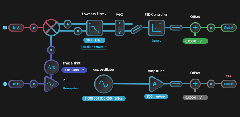
During the live demo, you may have noticed that there was a phase offset between the input and phase-locked signal on the Oscilloscope, even though the phase shifter on the Lock-in Amplifier was set to zero degrees. This offset is a result of lag from the PID loop. In reality, the feedback loop takes a finite amount of time to adjust the frequency. In the live demo, we used a simple gain block to amplify the error signal (i.e., only the “P” term in PID). This offset can be fixed by changing the PID parameters on the Lock-in Amplifier. By clicking on the settings icon in the top right of the Lock-in Amplifier menu, you can replace the gain block with the PID Controller, as seen in the screenshot below.
In the context of a control loop, what is a typical loop delay we can expect from Moku:Pro?
You can typically expect loop delays on the order of ~300 ns, depending on your settings.
We have multiple Moku:Go devices. Can we implement your demo using them?
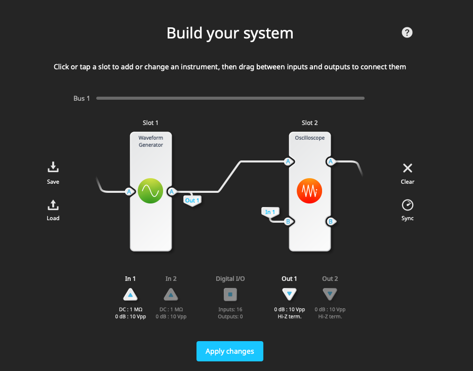
Yes! This should work fine so long as you keep in mind the lower bandwidth of Moku:Go (30 MHz vs. 500 MHz for Moku:Pro). The only other consideration is that, since there are only two slots in Multi-instrument Mode on each Moku:Go device, you will need to physically connect the devices with BNC cables. This may introduce phase delay and/or shifts, but this can be adjusted with the PID parameters. If you wish to replicate the demo on your Moku:Go, we recommend the following configuration for each: Moku:Go #1 This device handles the signal generation and detection. The signal from the Waveform Generator is fed to Input A of the Oscilloscope and Output 1. Output 1 will need to be physically connected to Input 1 of the second Moku, which will in turn feed the phase-locked signal back to input B of the Oscilloscope.
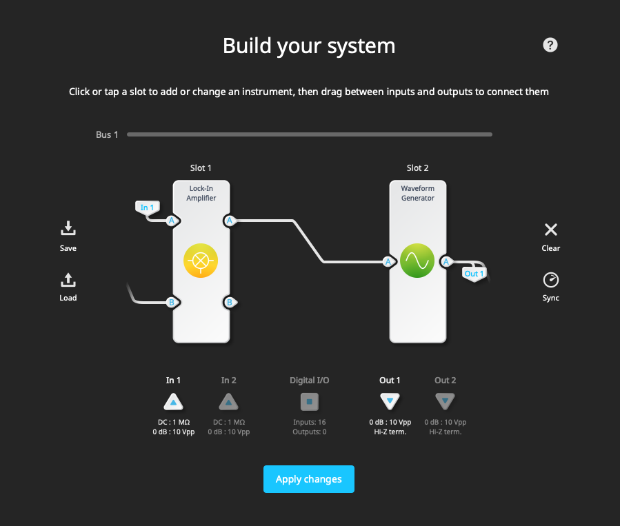
Moku:Go #2 This device acts as the feedback loop. The Lock-in Amplifier receives the signal via Input A and outputs the demodulated signal to the second Waveform Generator. The Waveform Generator, acting as the VCO, feeds its output back into Input B of the Lock-in Amplifier. It also sends the signal to Output 1 of the Moku device, which is then routed back to the first Moku device for detection.
When implementing a phase-locked loop, what criteria should guide the setting of the bandwidth for the lowpass filter?
In general, the bandwidth of the Lock-in Amplifier’s lowpass filter should be set as low as possible, such that the feedback loop of the PLL still functions. Making the lowpass filter higher than necessary will add noise to the error signal.
Can you lock to a varying DC signal?
Yes! The Phasemeter and the Lock-in Amplifier both have lower bounds on their frequency range (1 kHz and 1 mHz, respectively), so if you want to lock on to a DC signal, we recommend using the standalone PID Controller instrument.
Does Liquid Instruments take any custom requirements for a PLL? Can you add custom instruments to the FPGA?
We are always excited to hear about novel applications for our instruments, and are always working on improving and expanding the scope of Moku software. If you are interested in running custom FPGA code on your Moku device, check out Moku Cloud Compile. With Moku Cloud Compile, you can write your own code in VDHL and compile it on our website. After the code compiles, you can download a bitstream to deploy to your device.
On the Moku datasheet, the accuracy for phase measurement is around a µdegree. Could you please explain how this accuracy is calculated? Is it based on software algorithms, such as oversampling, or based on hardware?
All the measurements are done on the FPGA of the Moku device. The resolution of the phase relates to the phase resolution of the local oscillator (LO) in the PLL. If we know the phase of the LO in the PLL, we can determine the phase of the input signal, since the PLL will try to match the phase of the input signal. For this reason, the measured phase resolution is the same as the phase resolution of the PLL.
If I am running the Moku Laser Lock Box and I have a locked laser, then I exit the Laser Lock Box and I open a different instrument, will the Laser Lock Box stop working?
These are the types of applications that Moku Multi-instrument Mode was designed to solve. If you are running the Laser Lock Box (or the Lock-in Amplifier or Phasemeter) in Multi-instrument Mode, then you can switch to a different instrument and maintain the lock. As of Moku Version 3.1, you can even view all instruments simultaneously with multi-window viewing. If you are not in Multi-instrument Mode, then reconfiguring the Moku will cause the Laser Lock Box to stop working. Thank you for viewing our webinar. We look forward to seeing you again! For more insightful demonstrations, check out our webinar library for on-demand viewing.
More questions?
Get answers to FAQs in our Knowledge Base
If you have a question about a device feature or instrument function, check out our extensive Knowledge Base to find the answers you’re looking for. You can also quickly see popular articles and refine your search by product or topic.
Join our User Forum to stay connected
Want to request a new feature? Have a support tip to share? From use case examples to new feature announcements and more, the User Forum is your one-stop shop for product updates, as well as connection to Liquid Instruments and our global user community.