In this series, we provide a practical reference for designing and debugging loops by presenting a short introduction to feedback control as encountered in the frequency domain.
1.1 Introduction
From the excitement of operating a helicopter on another planet to essential everyday applications in power grids and domestic heating, feedback control systems are a necessary and ubiquitous part of modern society. In research and industry, control loops allow one to automate, reduce noise, improve performance and cope with uncertainty and parameter variation. However, concomitant concerns over complexity and possible instability must also be addressed.
This first installment in the series establishes the definition of a transfer function and provides the components from which one can construct control loop block diagrams to model elaborate systems. In Part 2 we demonstrate how feedback control systems can be used to suppress disturbances or track a process set point. The complications associated with noisy sensors are also discussed. Unlike open-loop systems, devices under feedback control have the potential to become unstable and there is tension between performance and robustness. Ultimately, delays in signal propagation can impose the most stringent limit. These issues are treated in Part 3. In the frequency domain, most parameters of a feedback system can be linked to its open-loop transfer function. In Part 4 we explain how to measure this important quantity and provide a list of functions often used in shaping it. Part 5 describes one method of avoiding actuator saturation and, in doing so, introduces ideas useful to the treatment of multiple actuators. Our series concludes in Part 6 with the study of the PID controller. This common control architecture is generally considered from a time-domain point-of-view; we illustrate the complementary frequency-domain representation.
1.2 Why frequency domain?
Linear, time-invariant dynamical systems, with a single input and single output (SISO) are predominantly described in terms of input/output differential equations of form
\(a_nfrac{d^ny}{dt^n}+ a_{n-1}frac{d^{n-1}y}{dt^{n-1}}+ldots+ a_1frac{dy}{dt}+a_0y= b_mfrac{d^mu}{dt^m}+ b_{m-1}frac{d^{m-1}u}{dt^{m-1}}+ldots+ b_1frac{du}{dt}+b_0u,\).
where u(t) is the input function, y(t) the output and\(a_i, b_iin mathbb{R}\) are constants.
Such equations can be difficult to solve directly. By exploiting the Laplace transform and its properties (see Appendix A), one can move to the frequency domain where purely algebraic solutions are possible.
Moreover, operation in the frequency domain enables simple methods for constructing and analyzing complex systems and concepts related to closed-loop stability may be more easily treated and understood.
1.3 What is a transfer function?
Taking the Laplace transform of (1.1) we obtain
\((a_ns^n+ a_{n-1}s^{n-1}+ldots+a_1s+a_0)Y(s) = (b_ms^m+ b_{m-1}s^{m-1}+ldots+b_1s+b_0)U(s)\),
where Y(s) and U(s) are our new output and input functions in the frequency domain. In order to consider only the response of the system to the input signal, we have assumed that the system is undisturbed at \(t=0^-\), i.e.\(y(0^-),dot{y}(0^-),text{etc}=0\). We have also assumed that the input u(t) is zero for t < 0 with \(u(0^-),dot{u}(0^-),text{etc.}=0\). This setup, with static initial conditions, is sometimes referred to as the zero state response. We define the transfer function H(s) to be the ratio of the output to the input
Another often-seen form of this equation is
\(H(s) = frac{N(s)}{D(s)}= K frac{(s-z_1)(s-z_2) ldots (s-z_{m-1})(s-z_m)}{(s-p_1)(s-p_2)ldots(s-p_{n-1})(s-p_n)}\).
This version, which rearranges the polynomials in the numerator and denominator to their root form, is known as the zero-pole-gain or zpk representation. The zeros of the system are the roots of N(s) = 0 and the system poles are the roots of D(s) = 0.
Since the coefficients of (1.1) are real, the poles and zeros are either real or occur as complex conjugate pairs.
Given its transfer function, one can compute a system’s response to arbitrary inputs, just as was possible using the differential equation representation. More often, we use the transfer function to evaluate the steady-state response, in terms of both magnitude and phase, to sinusoidal inputs. This frequency response may be computed by evaluating the transfer function at s = iω.
1.4 Loop algebra
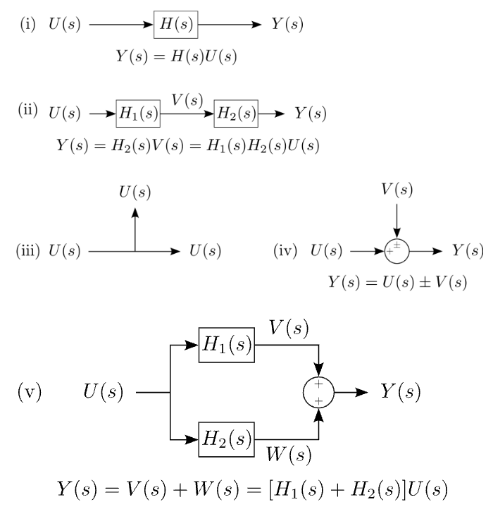
In the following parts of this series, we will represent systems using block diagrams. Each block represents a transfer function and they may be combined algebraically into arbitrarily complex systems. Some fundamental examples, such as serial, parallel, and additive connections, are shown in Figure 1.1.

Figure 1.1: The transfer function of a complex system may be constructed algebraically from fundamental components. (i) Single block, (ii) Series connection, (iii) Pick-off point, (iv) Summing node, (v) Parallel connection.
Appendix A: Laplace transform
The one-sided Laplace transform is \(F(s)=int_{0^-}^infty f(t)e^{-st},mathrm{d}t\)
Here s = σ + iω is the complex frequency, where σ and ω are real, and we have tacitly assumed that f(t) = 0 for t < 0. The unusual lower limit of t = 0−, i.e. just before t = 0, is taken to simplify our calculations. An alternative approach is to take the limit to be t = 0 but assert that any discontinuities in the input function occur at t = 0+.
The relationship between the Laplace and Fourier transforms may be characterized by
In a sense, the Fourier transform is a special case of the Laplace transform where σ=0, and we evaluate the steady-state response of a given control system under this condition. Some important functions in control theory, such as the unit step, have a Laplace transform but not a Fourier transform.


