Introduction
The Moku Gigabit Streamer provides fast, deterministic sample-data streaming over high-speed SFP and QSFP interfaces. It enables real-time wideband capture, high-rate sample playback, and distributed signal-processing across multiple devices. This Quick Start Guide details how to stream data between two Moku:Delta devices. We begin with a Moku-to-Moku link as it requires minimal network configuration and is the simplest way to get started with the Gigabit Streamer.
Two versions of Gigabit Streamer instrument are available on Moku:Delta:
- Gigabit Streamer, which utilizes the two 10 Gbit/s SFP ports
- Gigabit Streamer+, which utilizes the 100 Gbit/s QSFP port
Note that the Gigabit Streamer+ is subject to export control and restrictions.
Both versions integrate seamlessly with other Moku instruments through Multi-Instrument Mode, allowing streamed data to be generated, processed, and visualized within the same device. Because the SFP and QSFP interfaces connect directly to different physical areas of the FPGA, the Gigabit Streamer instruments must be placed in specific slots when deployed in Multi-Instrument Mode:
| Multi-Instrument Mode Slot | Instrument | Physical Port |
| Slot 1 | Gigabit Streamer | SFP1 |
| Slot 2 | Gigabit Streamer+ | QSFP |
| Slot 3 | Gigabit Streamer | SFP2 |
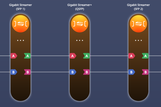
Figure 1. Gigabit Streamer and Gigabit Streamer+ configuration in Multi-Instrument Mode.
The Gigabit Streamer can only operate in 3-slot Multi-Instrument Mode on Moku:Delta, as it requires the full 5 GSa/s sampling rate. The Gigabit Streamer+ can also operate as a standalone instrument, where analog inputs 1–4 map to the record path and analog outputs 1–4 provide playback.
Connecting the devices
This Quick Start Guide walks through a Moku-to-Moku streaming setup. The physical configuration of a Moku-to-Moku streaming setup can be seen in Figure 2.
- Moku 1 generates a waveform using the Arbitrary Waveform Generator (AWG) and transmits the custom waveform through the Gigabit Streamer in Slot 3.
- Moku 2 receives the incoming stream through its own Gigabit Streamer in Slot 1 and displays the waveform on the Oscilloscope.
- All routing between instruments on each device is handled digitally inside Multi-Instrument Mode, with no external networking equipment required.
- The Moku are connected directly through their SFP ports using a 10G DAC cable. For reasons detailed below, ensure that SFP2 on Moku 1 connects to SFP1 on Moku 2. Once LED 3 on each device turns blue, the physical link is active and we can start data streaming.
- Connect the 10 MHz reference ports on both Mokus to synchronize the clocks. Use Moku 1 as the master unit, connecting Ref Out to Ref In on Moku 2.
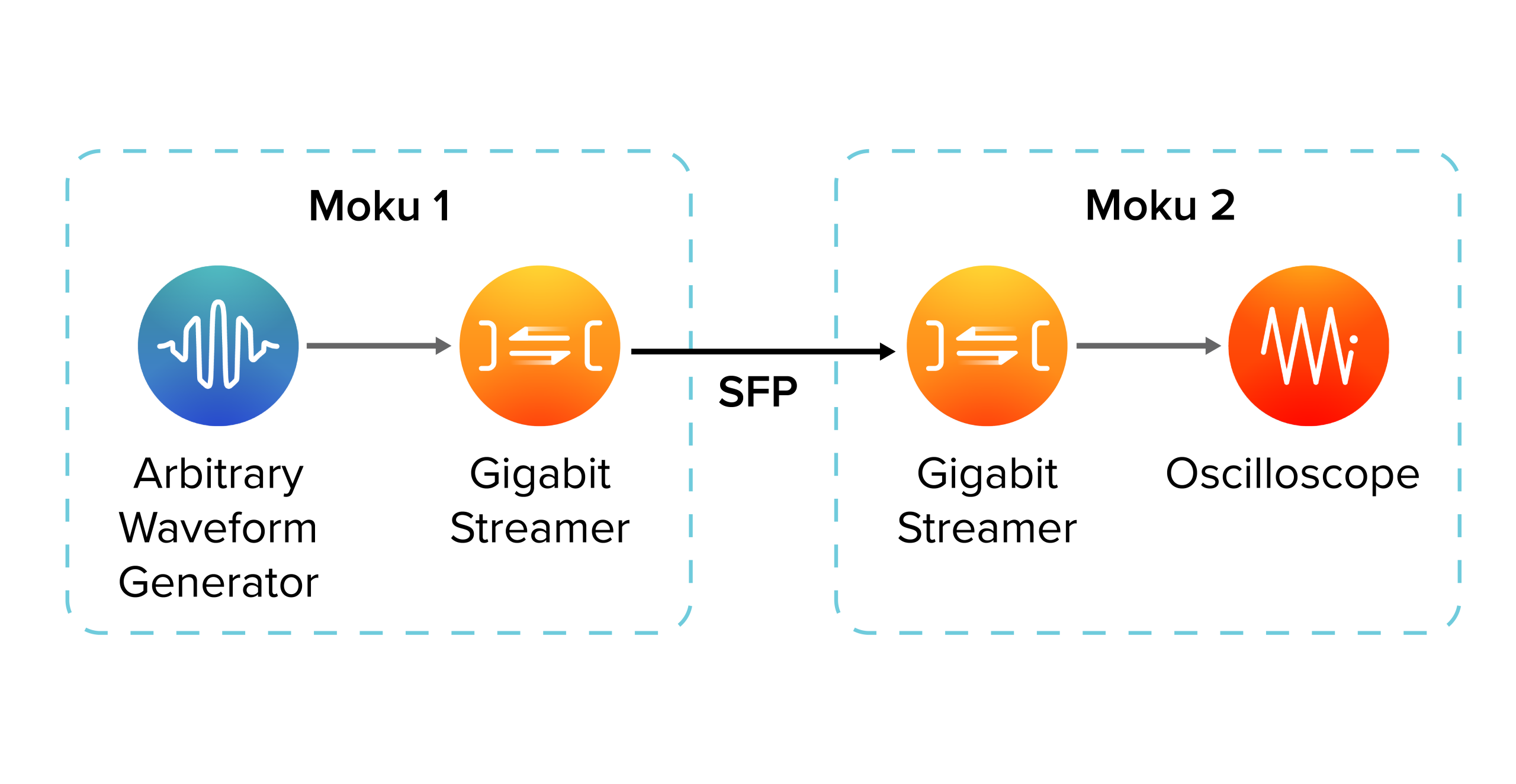
Figure 2. Configuration for Moku to Moku data streaming through Gigabit Streamer
Moku 1 configuration (transmit)
On Moku 1, place the Arbitrary Waveform Generator in Slot 2, then add the Gigabit Streamer to Slot 3, which corresponds to the SFP2 port. Ensure the outputs are routed to the Gigabit Streamer inputs. With the routing in place, configure the Arbitrary Waveform Generator to generate two signals, one on each channel.
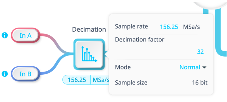
Figure 3. Decimation block setup for transmission.
Next, configure the streaming parameters. In the Decimation block shown in Figure 3, set the sample rate to 156.25 MSa/s, which corresponds to the maximum acquisition rate for two channel streaming over the SFP. Ensure that the signal frequencies produced by the Arbitrary Waveform Generator are below half of this rate to avoid aliasing.
Next, open the Gigabit Streamer interface and click the globe icon to access the network configuration required for the stream:
- Local
- IP address: 10.1.1
Assign a static IP for the SFP network (this is separate from the control interface IP). - Multicast Address: Leave empty
Not used for direct point-to-point links. - UDP Port: 4991
Any unused port is acceptable; Moku 1 does not receive packets in this example.
- IP address: 10.1.1
- Remote
- IP address: 10.1.2
Must match the Local IP configured on Moku 2. - UDP Port: 4991
Must match the Local UDP port on Moku 2.
MAC Address: MAC address of Moku 2’s SFP port
Copy this from the “Local MAC Address” field in Moku 2’s Gigabit Streamer.
- IP address: 10.1.2
- Network MTU: 1500 bytes
This is the maximum supported size for Moku-to-Moku reception; payload size and samples per packet are calculated automatically.
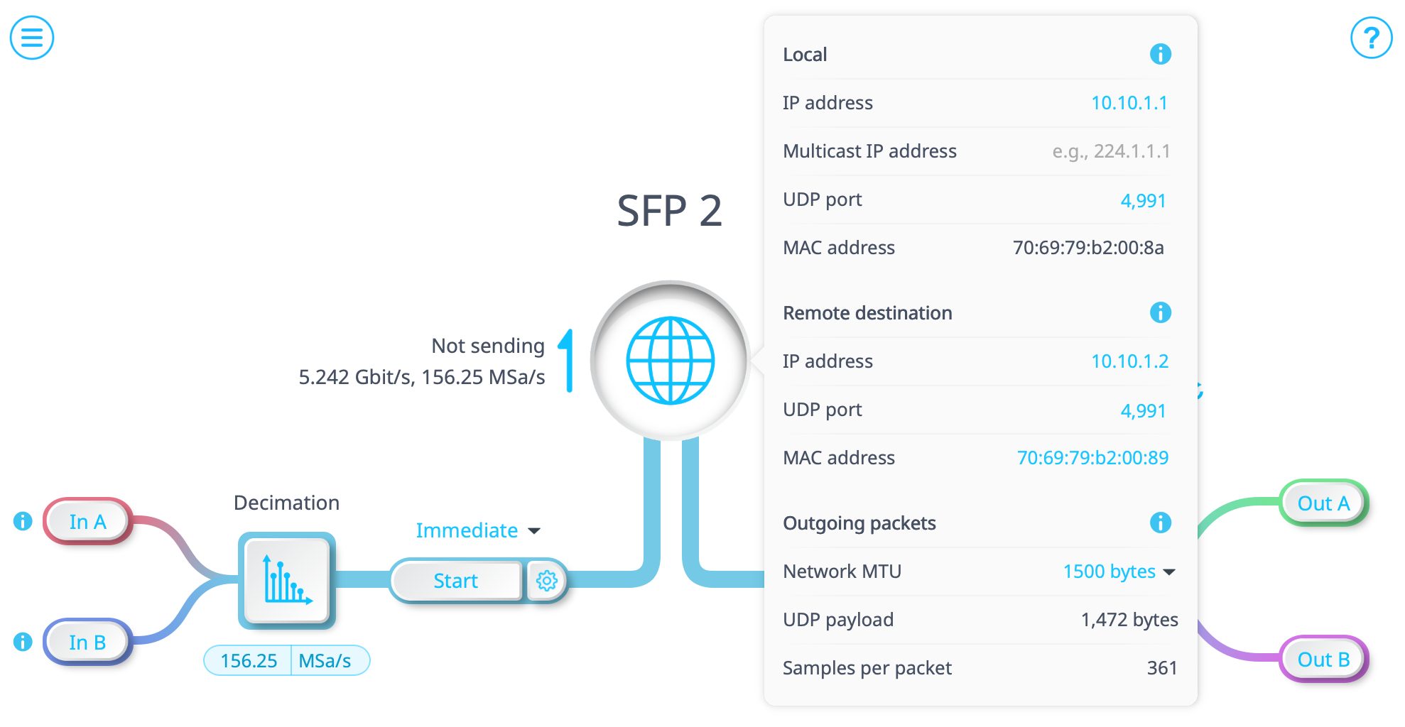
Figure 3 Network configuration for Moku 1 Gigabit Streamer for transmission
Moku 2 Configuration (Receive)
On Moku 2, we will configure the Gigabit Streamer to receive the incoming sample stream from Moku 1 and display it using the Oscilloscope. In Multi-Instrument Mode, add the Gigabit Streamer to Slot 1 (SFP1) and add the Oscilloscope to Slot 2, then connect the Gigabit Streamer outputs to the Oscilloscope inputs to complete the receive path.
We will then configure the Gigabit Streamer with the following network parameters:
- Local
- IP Address: 10.1.2
Assign a static IP for the dedicated SFP link. - Multicast Address: Leave empty
Not used for point-to-point links. - UDP Port: 4991
Must match the Remote UDP Port configured on Moku 1. - MAC Address: Fixed by Moku
Displayed automatically; each SFP or QSFP port has its own MAC address.
- IP Address: 10.1.2
- Remote
- IP Address: Leave blank
Not required on the receiving side. - Remote UDP Port: 4991
Not used, but often kept consistent with the Local UDP Port. - Remote MAC Address: Leave blank
Not required on the receiving side.
- IP Address: Leave blank
- Network MTU: 1500 bytes
This is the maximum packet size that the receiver can accept.
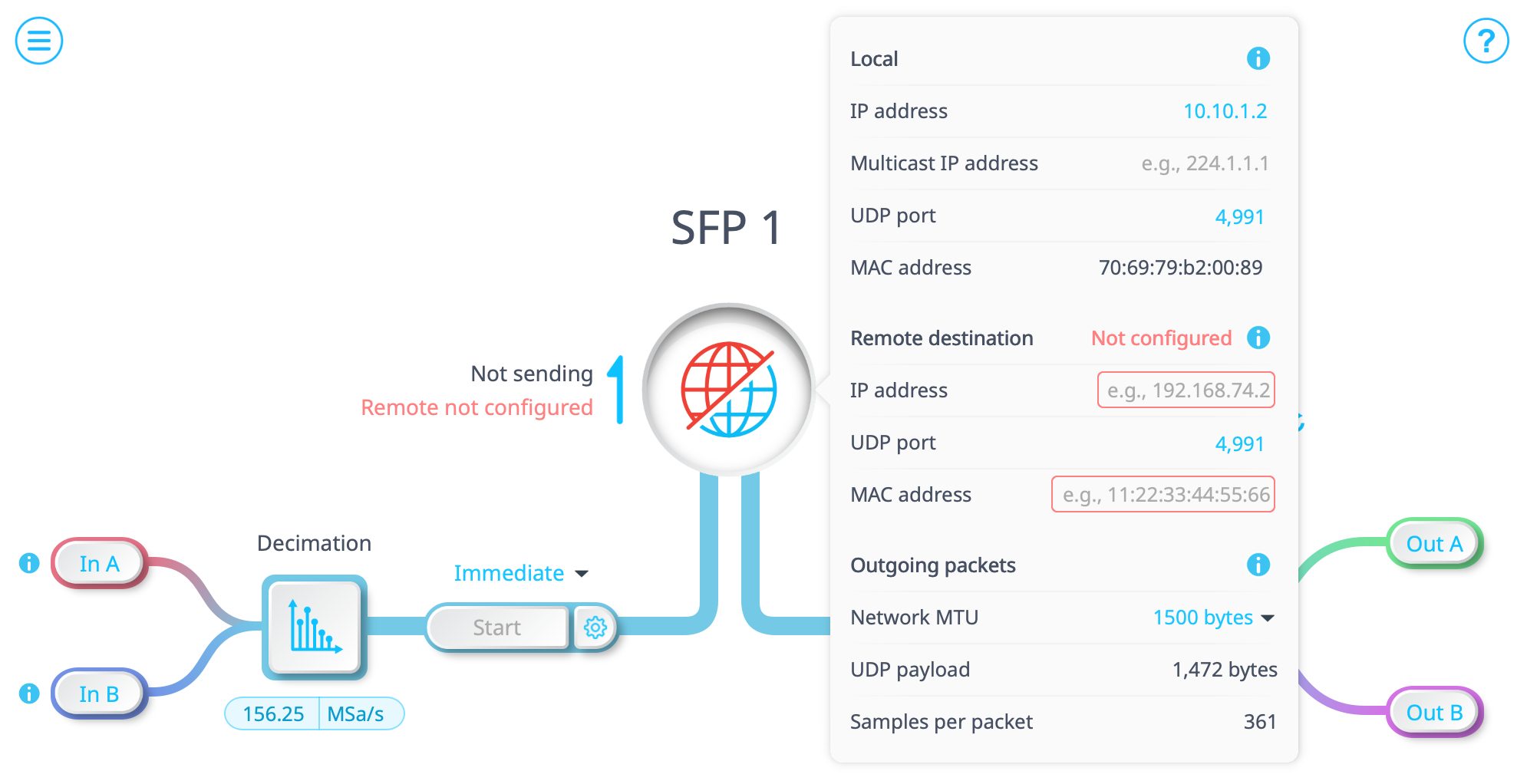
Figure 5. Network configuration for Moku 2 Gigabit Streamer for receiving
Once these settings are applied, the receiver is ready to accept an incoming stream. The output channels on Moku 2 can be enabled manually by clicking on Out A or Out B. However, the routing to the output ports is determined automatically by the transmitting Moku. When Moku 1 begins transmitting, if there is only one channel streaming, then only Out A will be enabled; if both channels are streaming, then both Out A and Out B will be connected automatically.
Now that we have configured both Mokus, start the streaming session by clicking “Start” on Moku 1 to begin transmitting, the receiver will feed the sample stream to the Oscilloscope in real time, and you should be able to see the arbitrary waveforms.

Figure 6. Arbitrary waveforms transmitted through Gigabit Streamers connected through the SFP ports and displayed in the Oscilloscope.
Summary
This Quick Start Guide outlined the configuration required to establish a direct streaming path between two Moku:Delta devices. By combining Multi-Instrument Mode routing with a high-speed SFP connection, the Gigabit Streamer forms a deterministic link for passing high-rate waveform data between devices.
The configuration shown here can be adapted to support different instrument combinations, or more complex test arrangements where generation and analysis are distributed across devices. The same principles apply regardless of the specific workflow, making the Gigabit Streamer a versatile component within larger measurement system.