The Moku Gigabit Streamer provides fast, deterministic sample data streaming between Moku:Delta and a Linux host computer over high-speed SFP or QSFP interfaces, with support for simultaneous transmit and receive operation. This guide explains how to configure and use the Gigabit Streamer to stream data reliably between the Moku and a host system, covering stream setup, packet structure, and practical considerations for both transmit and receive workflows.
Introduction
The Moku Gigabit Streamer provides fast, deterministic sample data streaming between a Moku:Delta and a host computer over high-speed SFP (Small Form-factor Pluggable) and QSFP (Quad Small Form-factor Pluggable) interfaces. It supports simultaneous transmit and receive operation on the same port, enabling real-time record and playback workflows.
Moku Gigabit Streamer is available in two versions, Gigabit Streamer and Gigabit Streamer+, both using the same packet structure and streaming model, with differences only in physical connectivity and maximum data rates.
The Gigabit Streamer uses the two SFP interfaces capable of streaming two channels of real-valued samples at data rates of up to 5 Gbit/s per port. It is suited for high-bandwidth acquisition and real-time streaming where a direct, efficient data path is required.
The Gigabit Streamer+ extends these capabilities with a QSFP interface that enables dual-channel streaming within Multi-Instrument Mode, or up to four channels in stand-alone operation, with a total data rate up to 80 Gbit/s. This is ideal for ultra-high-speed capture, demanding hardware-in-the-loop systems, and large-scale data processing workflows.
Both versions use User Datagram Protocol (UDP) over IPv4 and a DIFI-aligned VITA 49.2 packet structure with fixed-rate transport, low latency, and predictable timing. When used in Multi-Instrument Mode, the Moku Gigabit Streamer enables real-time capture, waveform playback, sensor simulation, and distributed processing using an external system.
This guide provides a complete overview of how to configure, verify, and operate a high-speed streaming link between a Moku:Delta and a host computer. It covers essential transmission concepts, packet structure, and practical setup steps for both transmit and receive operation. This guide is based on Linux OS to enable more flexible network configuration, please modify accordingly if you are using a different operating system.
Hardware setup
The Moku:Delta provides two SFP ports and one QSFP port for high-speed data transport. The Moku Gigabit Streamer uses the SFP interfaces, while the Moku Gigabit Streamer+ operates through the QSFP interface.
- Gigabit Streamer, which utilizes the two 10 Gbit/s SFP ports
- Gigabit Streamer+, which utilizes the 100 Gbit/s QSFP port
The SFP and QSFP ports connect to dedicated regions of the FPGA on Moku:Delta. Because of this fixed hardware routing, the Gigabit Streamer and Gigabit Streamer+ must be placed in specific slots when used in Multi-Instrument Mode. Unlike most Moku instruments, they cannot be deployed in arbitrary slots.
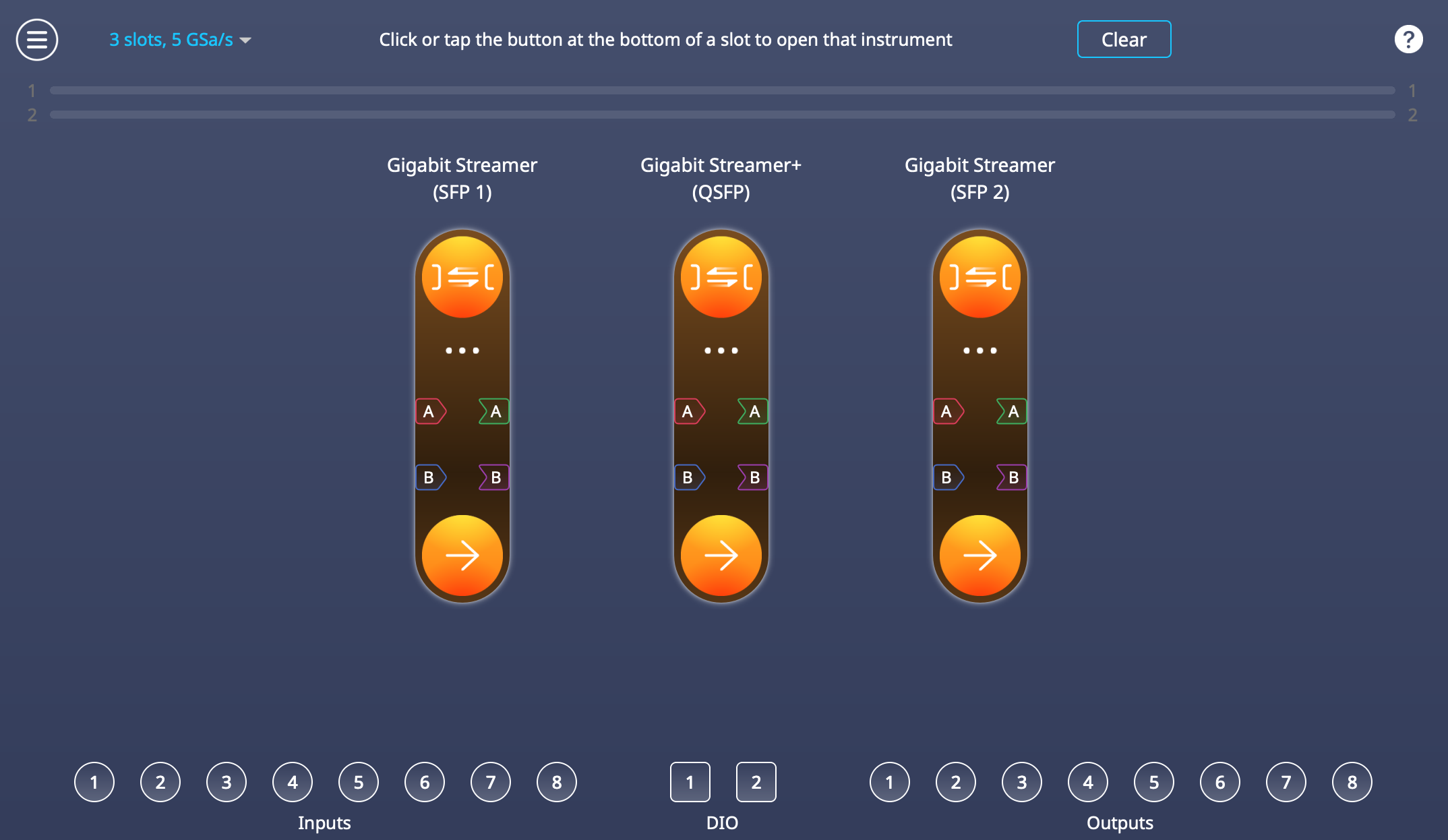
Figure 1 Gigabit Streamer and Gigabit Streamer+ allocation in 3-slot Multi-Instrument Mode
Table 1 Instrument mapping in 3-slot Multi-Instrument Mode
| Multi-Instrument Mode Slot | Instrument | Physical Port |
| Slot 1 | Gigabit Streamer | SFP1 |
| Slot 2 | Gigabit Streamer+ | QSFP |
| Slot 3 | Gigabit Streamer | SFP2 |
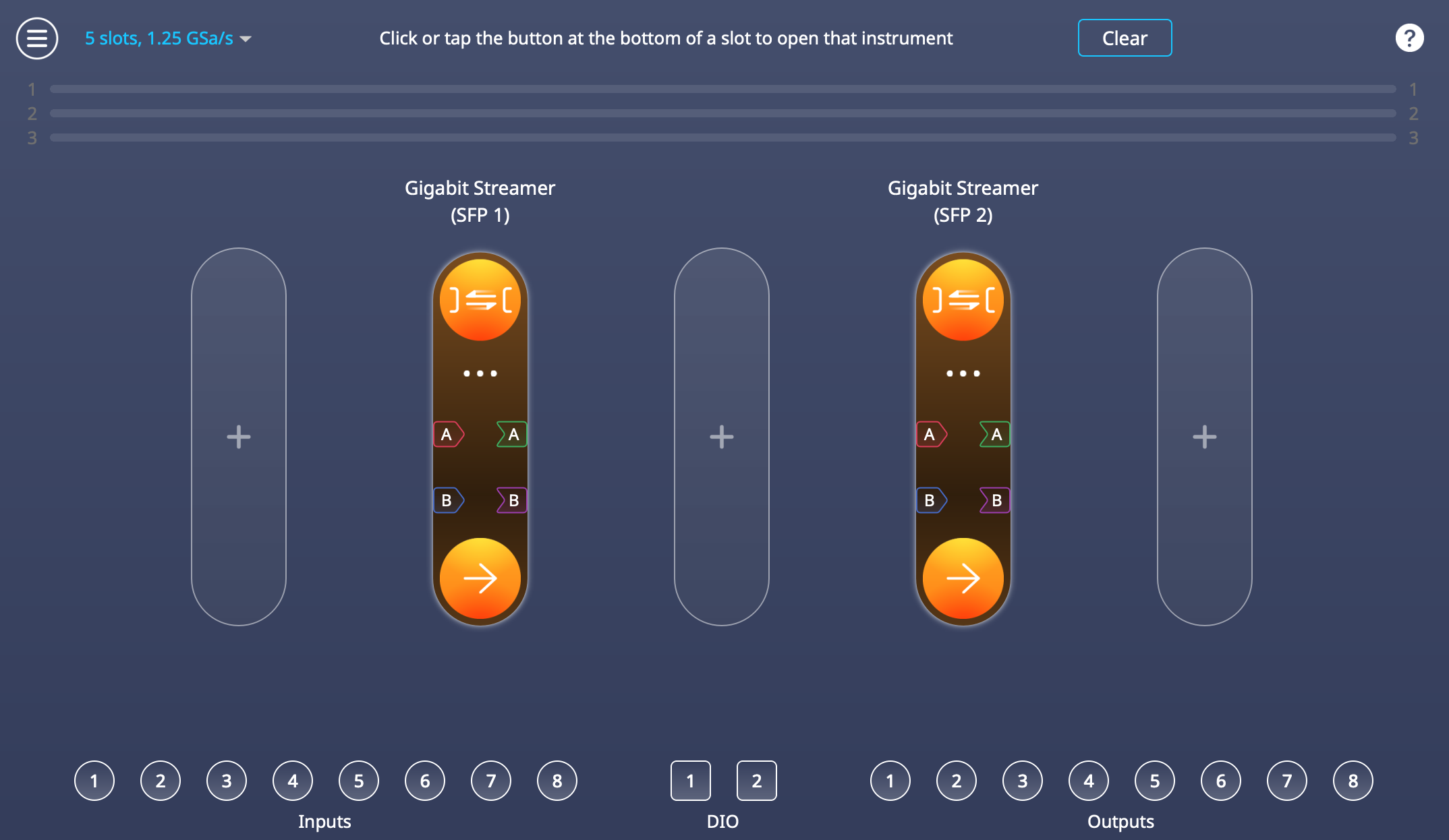
Figure 2 Gigabit Streamer allocation in 5-slot Multi-Instrument Mode
Table 2 Instrument mapping in 5-slot Multi-Instrument Mode
| Multi-Instrument Mode Slot | Instrument | Physical Port |
| Slot 2 | Gigabit Streamer | SFP1 |
| Slot 4 | Gigabit Streamer | SFP2 |
Gigabit Streamer+ can also run in standalone mode, during which it occupies the full FPGA fabric and always operates through the QSFP port.
Host computer recommendations
A high-rate UDP stream requires a host with enough input and output rate, and processing capacity to receive and store continuous data without interruption. This section provides guidelines for a host configuration suitable for sustained high-rate UDP reception. Requirements may scale with line rate and application load. The overall performance depends on the Network Interface Card (NIC), CPU, system memory, and storage working together without creating bottlenecks.
Network interface
The host requires an SFP+ or SFP28 NIC for the Moku Gigabit Streamer, or a QSFP28 NIC for the Gigabit Streamer+. These interfaces must support direct-attach copper (DAC) cables, since DAC links are required for streaming.
The NIC should be installed in a PCIe slot with enough bandwidth for the intended link rate.
CPU and interrupt handling
High-rate UDP capture relies on the host CPU to receive packets, buffer incoming data, and pass samples into user space. For reliable streaming, the host system should provide sufficient processing capacity to keep up with the incoming data rate.
In practice, this is best achieved with:
- A multi-core CPU with good single-thread performance
- Network interface card drivers that support receive-side scaling
- Well-distributed interrupts to ensure processing load is shared across CPU cores
For higher-rate QSFP links, workstation- or server-class processors offer additional headroom, particularly for long-duration or continuous captures.
System memory
Buffering incoming network data relies on available system memory to absorb short packet bursts and accommodate momentary delays when writing data to disk. Providing adequate memory helps maintain continuous, loss-free streaming.
Storage throughput
Reliable storage throughput helps maintain smooth data flow throughout the capture process, the appropriate storage configuration depends on the target streaming rate and the intended capture duration. For most high-speed streaming applications, this is achieved by using storage solutions that support continuous, large-block sequential writes at the required throughput. At higher line rates, additional storage bandwidth may be beneficial, such as higher-performance devices or multiple drives operating together.
Connecting the hardware
Host-to-Moku streaming uses a direct point-to-point Ethernet connection between the Moku and the host computer. This connection does not require any network switches or routers and is configured as a dedicated link for high-rate data streaming.
Connect the host network interface card directly to the corresponding SFP or QSFP port on the Moku:Delta using a supported DAC cable. If the host computer does not have a native SFP or QSFP port, install a compatible adapter that is supported by the operating system.
For Moku Gigabit Streamer (SFP version):
- A compatible 10G SFP+ or SFP28 DAC cable
- A host computer with an SFP+ or SFP28 NIC that supports DAC cable
For Moku Gigabit Streamer+ (QSFP version):
- A compatible 100G QSFP28 DAC cable
- A host computer with a QSFP28 NIC that supports DAC cable
When the connection is established, LED 3 on the Moku front panel turns blue, indicating an active link. You can also confirm the link status from the host computer network interface. The example below uses an interface named “enp5s0f0np0”, replace this with the name of your actual interface.
- Find the interface with:
ip addr
Look for an entry that corresponds to the SFP or QSFP port connected to the Moku:Delta, for example:
enp5s0f0np0 : <BROADCAST,MULTICAST,UP,LOWER_UP> mtu 1500 ...
UP and LOWER_UP indicate that the interface is enabled and has a link.
- Check link status and speed
Use ethtool to confirm that the physical link is active and to read the negotiated speed:
sudo ethtool enp5s0f0np0
Key fields to check:
-
- Link detected: yes
- Speed: 10000Mb/s or 100000Mb/s (depending on SFP or QSFP link)
- Duplex: Full
QSFP configuration for Moku Gigabit Streamer+
The QSFP interface on the Moku:Delta does not use Forward Error Correction (FEC). If the host NIC enables FEC by default, the link may not come up. Most NICs allow FEC to be disabled with the following sequence to first bring the interface down, then disable FEC, and finally bring the interface back up. Replace <interface> with the name of your interface, e.g. enp7s0f0np0.
sudo ip link set <interface> down
sudo ethtool --set-fec <interface> encoding off
sudo ip link set <interface> up
The interface should now report link detected and the configured speed. Once the physical link is stable, you can proceed to IP configuration and Gigabit Streamer setup.
Transmission configuration with static IP addressing
High-rate data streaming on the Moku Gigabit Streamer uses a direct, fixed-parameter UDP link between the Moku:Delta and a host computer. The SFP and QSFP ports used for streaming from a point-to-point Ethernet connection, and only the configured peer can send or receive packets on that port. This approach provides predictable timing, low protocol overhead, and consistent throughput.
The Gigabit Streamer operates using static IP addressing on its streaming ports. These ports are configured for deterministic data transfer and therefore do not use automatic address discovery mechanisms such as ARP or DHCP.
For correct operation, the Moku and the host must be configured with IP addresses that reside on the same subnet for the streaming interface.
Transmit mode (Moku to host):
The host communicates with the Moku using the configured IP address and receives UDP packets on the specified port. This configuration is handled directly through the Moku App, and usually no additional host-side network configuration is required.
Receive mode (host to Moku):
To send data to the Moku, in addition to configuring the streaming port in the Moku App, the host must associate the Moku streaming IP address with its corresponding MAC address using a static neighbor entry. This ensures packets are delivered correctly over the direct link.
This association is required each time the Receive-mode streaming connection is established, such as after reconnecting the cable or restarting either the host or the Moku.
To check the current neighbor table on the host, run:
ip neighbor | grep <moku_NIC_IP>
If the entry is INCOMPLETE, replace it by running:
sudo ip neigh replace <moku_NIC_IP> lladdr <moku_MAC> dev <interface> nud permanent
For example, suppose you configure the Gigabit Streamer in the Moku app with:
- Local IP address: 10.10.1.1
- Local MAC address: 70:69:79:b2:02:69
If the host computer is using the network interface enp5s0f0np0 to transmit data to Moku:Delta, you must add a static neighbour entry so the host can resolve Moku:Delta’s IP address to its MAC address:
sudo ip neigh replace 10.10.1.1 lladdr 70:69:79:b2:02:69 dev enp5s0f0np0 nud permanent
This ensures that packets sent to 10.10.1.1 are transmitted to the correct destination MAC address on the specified interface.
Packet and data structure
The Moku Gigabit Streamer uses a DIFI-aligned VITA-49.2 packet format for all transmitted and received sample data, transported using UDP over IPv4. Two packet types are used: Context packets, which describe the configuration of the stream; and Data packets, which carry the sample payload. Both packet types follow fixed layouts, and the host must parse them correctly in order to interpret and reconstruct the data stream.
Sample data is transmitted as a continuous stream of UDP packets at a fixed rate. The streaming rate is defined by the selected sample rate, sample size, number of channels, and the configured maximum transmission unit (MTU). The MTU determines the maximum UDP payload size, and therefore how many samples are placed in each packet.
The streaming link operates without reliability or flow-control mechanisms such as acknowledgements, retransmission, or Ethernet pause frames. Packets are transmitted at the configured rate for the duration of the stream, and the host system needs to be able to receive and process the data continuously at that rate.
Packet interpretation sequence
The Gigabit Streamer data stream is defined and interpreted by processing packets in a consistent sequence:
- Context packet
The Context packet is processed first and establishes how subsequent Data packets are interpreted. It provides the stream identifier, sample rate, data format, scaling parameters, and Data Packet Payload Format. These fields describe the sample type, item size, fractional size, channel tagging, and vector size, which together define how samples are packed within each Data packet.
- Data packet header
Each Data packet header is then read, with the stream identifier used to associate the packet with the active Context information.
- Data packet payload
Sample values are unpacked according to the defined packing format. For multi-channel streams, samples are deinterleaved in the order described by the Context packet.
- Applying Context parameters
The sample rate, scaling, and gain information from the Context packet are applied to place samples in time and reconstruct physical signal values.
This ordering is also reflected in the packet structure and layouts described in the following sections.
Overall packet structure
Sample data and stream metadata transmitted by the Gigabit Streamer are encapsulated within standard Ethernet, IP, and UDP headers. Figure 3 illustrates this encapsulation hierarchy and highlights the protocol overhead associated with each packet.
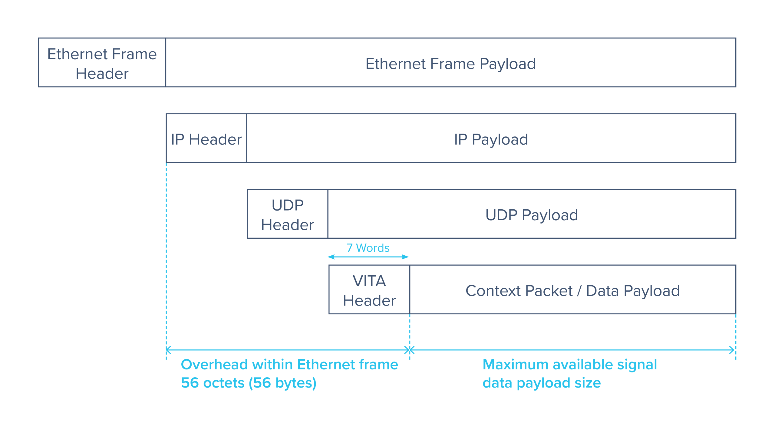
Figure 3 Moku Gigabit Streamer packet structure, which follows DIFI Protocol stack packet structure.
Ethernet frame
The Ethernet frame provides the outermost link-layer encapsulation. It consists of an Ethernet frame header followed by the Ethernet frame payload, which carries the IP packet. All protocol overhead shown in Figure 3 is contained within the Ethernet frame payload.
Internet Protocol layer
The Internet Protocol layer encapsulates the UDP datagram and provides logical addressing between the Moku:Delta and the host computer. The fixed header size contributes to the overall protocol overhead within each Ethernet frame.
User Datagram Protocol (UDP) layer
The UDP layer provides lightweight transport of the VITA packet. The UDP header precedes the UDP payload, which contains exactly one VITA packet.
VITA layer
The VITA layer defines the structure and interpretation of the streamed content. Each UDP payload contains a single VITA packet consisting of a VITA header followed by a VITA payload.
The VITA header has a fixed size of seven 32-bit words and is present in all VITA packets. The VITA payload carries either context information or signal sample data, depending on the packet type. This distinction is indicated within the VITA header itself.
Packet overhead and payload size
As shown in Figure 3, the combined Ethernet, IP, UDP, and VITA headers contribute a fixed overhead of 56 octets (56 bytes) within each Ethernet frame when using IPv4. The remaining space within the Ethernet frame payload determines the maximum available signal data payload size. Since every packet follows the same structure, selecting a larger MTU reduces the relative header overhead and improves overall streaming efficiency.
Context Packet
A Context packet defines the metadata associated with the current streaming session. It is sent at the start of every Gigabit Streamer streaming session. The Context packet does not contain sample data. Instead, it provides the information required to decode the payload format and timing of the data packets that follow.
The Moku Gigabit Streamer layout follows the VITA-49.2 Context Packet Class 0x0001 structure and is detailed below:
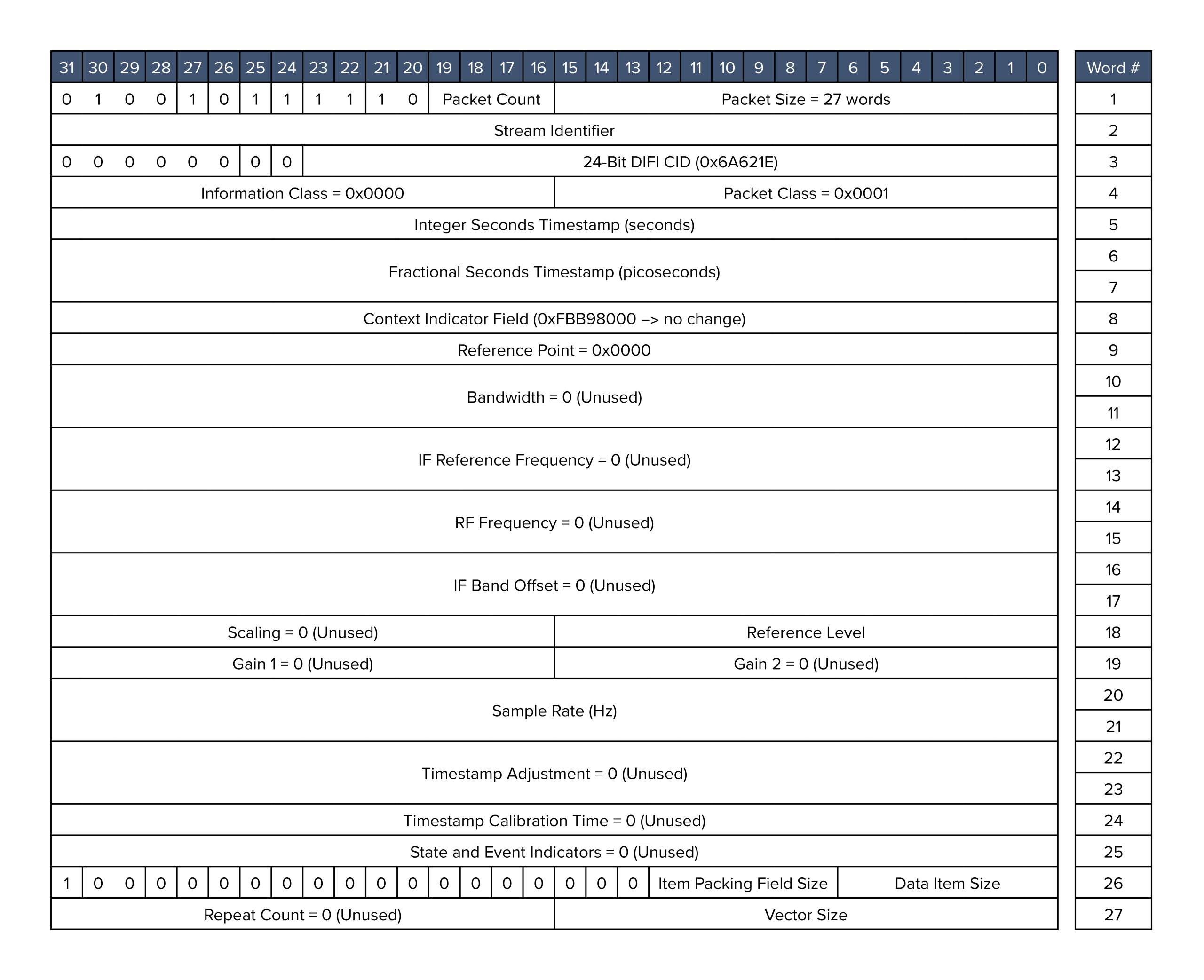
Figure 4 Moku Gigabit Streamer context packet structure
Table 3 Moku Gigabit Streamer context packet field definitions
| Field | Description |
| Packet Count | Increments (modulo 16) each time a context packet is transmitted. |
| Stream Identifier | Identifies the specific data stream. The Stream Identifier must match between the context packet and the corresponding data packets within the same streaming session. |
| Integer Seconds Timestamp | The number of seconds elapsed since epoch (time zero), defined as when the instrument was deployed or last reset. |
| Reference Level | AC power of a sine wave that produces a full-scale digitized sine ( Peak amplitude ± 2N−1), where N is the number of bits, referenced to a 50 Ω load. |
| Item Packing Field Size | Specifies the number of bits allocated per item in the stream, encoded as (sample bit width − 1)
Normal mode uses 15 (0b001111) and Precision mode uses 31 (0b011111). |
| Data Item Size | Specifies the number of bits actually used by each sample, encoded as (sample bit width − 1)
Normal mode uses 15 (0b001111) and Precision mode uses 31 (0b011111). |
| Vector Size | The number of channels minus 1 (0 for single-channel streaming, and 1 for dual-channel streaming) |
Data Packet
Each Data packet begins with a compact header describing how the sample payload is arranged. The header follows the same structure as the context packet header and provides parameters needed for correctly unpacking and interpreting the sample block. These fields define how individual samples are encoded and how many appear in the payload.
Figure 5 details the data packet structure used in Moku Gigabit Streamer, which is closely aligned with DIFI Packet Class 0x0000, standard flow signal data packet.
Figure 5 Moku Gigabit Streamer data packet structure.
Table 4 Moku Gigabit Streamer data packet field definitions
| Field | Description |
| Packet Count | Increments (modulo 16) each time a context packet is transmitted. |
| Stream Identifier | Denotes the specific stream. The Stream Identifier must match between the context packet and the data packet. |
| Integer Seconds Timestamp | The number of seconds passed since epoch (when time zero occurs), which is when the instrument was deployed or last reset. |
Sample Payload Format
The data payload contains a sequence of sample values encoded according to the parameters described in both the Context packet and the Data packet header. The Gigabit Streamer transmits real-valued samples using either 16-bit or 32-bit representations, depending on the decimation mode. Sample packing is deterministic, and the number of samples in each Data packet is determined by the selected MTU and the sample size.
Channels are interleaved in packet order. For example, in a two-channel stream the payload is arranged:
CH1[0], CH2[0], CH1[1], CH2[1], …
This interleaving method applies to all multi-channel configurations, including Gigabit Streamer+ four-channel streams.
Transmitting Data from Moku to a Host
With the packet structure and stream format defined, this section focuses on configuring data transmission from the Moku to a host computer. The Gigabit Streamer supports simultaneous transmit and receive operation on the same streaming interface; however, the configuration steps in this section describe transmit operation only and we will cover the receiving setup in the next section.
In transmission mode, the Moku streams sample data over the dedicated SFP or QSFP link using fixed network and stream parameters configured in the Moku App or APIs. The following steps outline how to set up the transmit path and prepare the host to receive and interpret the incoming data stream.
Moku Configuration (Transmit)
The signal to be transmitted can be routed through Multi-Instrument Mode, or defaults to the analog inputs as a standalone instrument for Gigabit Streamer+. If the signal arrives through an analog port, please confirm that the input range, coupling, and attenuation settings are appropriate for the source signal first.
Click the globe icon in the Gigabit Streamer interface to configure the network parameters. These parameters define the network identity of the Moku interface and the destination on the host computer.
Local:
- IP Address
Assign a static IP address for the SFP/QSFP port, this must be under the same subnet as the host. - UDP Port
Used for receive only. - MAC Address
Fixed by Moku to the specific SFP/QSFP port being used.
Remote Destination:
- IP Address
Set this to the host NIC’s IP address. - UDP Port
Set this to the port the host software will listen on. - MAC Address
Enter the MAC address of the host NIC connected to the Moku. The Gigabit Streamer does not perform ARP, so this field must be set explicitly.
Outgoing Packages:
- Network MTU
Select one of the supported MTU sizes, use the largest MTU supported by your network infrastructure and host. - UDP Payload
Calculated based on the MTU and sample size. - Samples Per Packet
Calculated based on the MTU and sample size.
The UDP port identifies the destination within the host application. Any unused port may be selected for Gigabit Streamer operation. In VITA-49 and related VRT workflows, port 4991 is commonly used as a convention, but this is not required. The Gigabit Streamer will transmit or accept packets on whichever port is configured.
Sample Format and Decimation
The Gigabit Streamer includes a Decimation block that sets the sample rate and sample width for the outgoing stream. All data routed into the streamer passes through this block before packetization. The decimation process is configured through both the sample mode and the decimation factor.
Decimation Mode
The decimation mode sets the numerical format of each output sample:
- Normal mode:
Produces 16-bit real samples.
Downsampling is performed by direct downsampling, where every D-th input sample is retained without filtering. - Precision mode:
Produces 32-bit real samples.
Downsampling is performed by block averaging, where each output sample is the average of D consecutive input samples. This improves numerical precision at lower effective rates.
Decimation Factor
The decimation factor D sets how the input sampling rate is reduced. The Gigabit Streamer supports factors that are either:
- A power of two (1, 2, 4, 8, 16, 32, …), or
- A multiple of 16 (16, 32, 48, 64, 80, 96, …)
For any valid factor D, the decimation block produces an output stream with rate:
(effective_rate (Sa/s) = input_rate (Sa/s) ⁄ D)
The network throughput is:
(stream rate (bit/s) = effective rate (Sa/s) × sample size (bits/Sa) × channel count)
This calculation determines the required host-side bandwidth.
When using decimation, aliasing can influence the resulting signal bandwidth. For broadband or high-frequency signals, choosing suitable decimation and sample mode settings helps maintain the desired frequency content.
Receiving Data on a Moku from a host computer
For applications like sensor emulation, closed-loop control testing, and wideband waveform playback, the Gigabit Streamer can be used in Receive mode to feed externally generated or pre-recorded data into the Moku:Delta.
The receive path has different network requirements from transmission, as the Moku does not participate in ARP and does not announce its presence on the link. A host sending data must construct packets that match the Gigabit Streamer’s expected format and deliver them directly to the streaming interface.
Host configuration
Host Interface
Identify the required host network parameters, including the IP address and MAC address of the NIC connected to the Moku, using:
ip addr
This command displays all network interfaces along with their assigned IP addresses and hardware (MAC) addresses.
You can also assign a static IP address on the host NIC connected directly to the Moku:
sudo ip addr add <sub_net> dev <interface>
sudo ip link set dev <interface> up
This configures the specified subnet on the selected interface and ensures that traffic destined for that subnet is routed through the correct NIC.
MTU Configuration
Match the MTU used by the Gigabit Streamer, note the maximum MTU Moku can accept is 1500 bytes.
sudo ip link set dev <interface> mtu 1500
A mismatched MTU can cause packet drops.
Static Neighbor Entry (ARP Replacement)
Moku’s receive ports operate without ARP resolution. If a host attempts to send packets using ARP-based MAC mapping, packets will remain in an incomplete state and do not reach the Moku. This requires the host to use a static MAC address when sending packets to the Moku.
First check the neighbor table:
ip neighbor | grep <moku_NIC_IP>
If an incomplete entry appears, replace it with a static entry:
ip neighbor replace < moku_NIC_IP> lladdr <MOKU_MAC> dev <interface> nud permanent
Moku Configuration (Receive)
The Gigabit Streamer can receive data using either point-to-point (unicast) or multicast transmission. The following sections describe the configuration workflow for each option, outlining the required host network setup and Gigabit Streamer settings so that data is delivered to the correct interface and address in each case.
Point-to-point (unicast)
In a receive-only workflow, only the Local IP, Local UDP Port, and Local MAC Address fields are relevant, whereas the remote destination settings are not used and can remain as not configured.
Click the globe icon in the Gigabit Streamer interface to configure the network parameters. These parameters define the network identity of the Moku interface and the destination on the host computer.
Local:
- IP Address
Assign a static IP address for Moku’s SFP/QSFP port, this must be under the same subnet as the host. - Multicast Address
Covered in more detail below. - UDP Port
The host must send packets to this port, the VITA-49.2 convention is to use port 4991, but any UDP port is valid, as long as it matches the destination port in the transmitted packet. - MAC Address
Fixed by Moku to a specific SFP/QSFP port.
Remote Destination (can leave unconfigured if used strictly in receive mode):
- IP Address
Optional, matches the host port IP address. - UDP Port
Optional, set this to the port the host software will listen on. - MAC Address
Optional, enter the MAC address of the host NIC connected to the Moku.
Outgoing Packages:
- Network MTU
Select one of the supported MTU sizes, Moku accepts MTUs up to 1500 bytes. - UDP Payload
Calculated based on the MTU and sample size. - Samples Per Packet
Calculated based on the MTU and sample size.
Multicast
The Gigabit Streamer also supports multicast streaming, allowing a host computer to transmit data to one or more receivers using a multicast IP address. To use multicast, the host operating system must be configured to route the selected multicast traffic to the correct network interface, and the same multicast address must be configured on both the host and the Gigabit Streamer.
First, configure the host to route multicast traffic to the desired network interface. For example:
sudo ip route add 224.1.2.0/24 dev enp129s0f0np0
This command redirects all multicast traffic in the range 224.1.2.X to the network interface enp129s0f0np0. The /24 prefix specifies how many of the most significant bits of the address must match. A broader range can be routed using 224.0.0.0/4 to cover all multicast addresses, or a single multicast address can be targeted using /32, for example 224.1.2.3/32.
Next, configure the Gigabit Streamer by entering the desired multicast IP address, such as 224.1.2.3, into the multicast IP address field.
Finally, transmit data from the host computer as normal, but use the configured multicast IP address as the destination address. The Gigabit Streamer will receive packets sent to this multicast address on the configured interface.
Sending Data from the Host
When sending data from the host to the Moku, the incoming stream follows the packet format described in the packet and data structure section. Data is delivered as an ordered sequence of Context and Data packets that together define and carry the sample stream.
The transmission sequence is as follows:
- Context packet
Transmission begins with a Context packet, which defines the stream configuration used by the Moku. For host-to-Moku transmission, the Moku accepts 16-bit sample data.
- Data packets
The Context packet is followed by a continuous sequence of Data packets using the same stream identifier. These packets are sent at a steady rate that matches the configured sample rate to maintain continuous playback.
- Packet sizing
Data packets should be constructed to match the configured maximum transmission unit so that payload sizing aligns with the selected network settings.
Moku processes incoming data at a fixed sample rate and in packet order, without performing rate adaptation or resampling. For this reason, host applications should apply rate control or throttling when transmitting Data packets, so that the send rate matches the configured stream rate. Providing steady packet timing helps the Gigabit Streamer apply the incoming data smoothly and avoids overflow or underflow, which can affect downstream instruments.
Note, the output connections of the Moku Gigabit Streamer (between the Interpolation block and the output ports) are automatically connected based on the “vector size” of the received context packet, not through the Moku App. Here the Gigabit Streamer will connect the specified number of channels, starting from Output A, then Output B, and so on based on the vector size parameter.
I/Q Handling (DIFI Compatibility)
The Moku Gigabit Streamer follows the VITA-49.2 packet structure and is closely aligned with DIFI. It can process DIFI packets by interpreting the I and Q components of a complex stream as two separate real-valued channels. When a complex stream is received, the I component is routed to Output A and the Q component to Output B automatically.
Analysis of Received Data
Once the Gigabit Streamer begins receiving valid data packets, these outputs can be connected to other instruments through Multi-Instrument Mode for validation and analysis.
For example, you can use:
- Oscilloscope for time-domain inspection of the received waveform
- Spectrum Analyzer for real-time frequency-domain analysis
- Analog outputs to connect to external equipment
Depending on the number of slots available, it’s possible to combine Gigabit Streamer with simultaneous time-domain capture, spectral monitoring, and hardware-in-the-loop operation.
Troubleshooting
This section outlines some common issues that might occur when configuring or operating the Gigabit Streamer and provides targeted checks to isolate and resolve them.
Link does not come up
If the physical link reports DOWN or LOWER_DOWN, check:
- Cable and NIC Compatibility
Verify that the cable is a supported DAC type and confirm that the NIC accepts passive DACs at the selected line rate.
- FEC Mismatch (QSFP Only)
QSFP operation requires FEC disabled on the host NIC.
Confirm FEC is disabled with:
sudo ethtool --show-fec <interface>
- Interface State
Bring the NIC up:
sudo ip link set dev <interface> up
Confirm link status:
sudo ethtool <interface>
If the link cannot negotiate, revisit the NIC line-rate configuration and ensure Gigabit Streamer is deployed to the correct slot in Multi-Instrument Mode, as this maps to specific SFP and QSFP ports.
Packets not reaching the host (transmit path)
If the Moku is transmitting but the host sees no packets:
- Incorrect IP / MAC configuration
IP and subnet must match exactly, and the MAC addresses must match exactly.
The host must be listening on the same port configured as the Remote UDP Port in the Moku App.
- MTU mismatch
If the MTU on the host side is smaller than the configuration in Moku, the host will not be able to accept the data packets.
- Firewall / interface binding
Ensure the receive application is bound to the correct interface and not the default route.
Packets not reaching the Moku (receive path)
The most common cause is missing neighbor-resolution due to the Moku not responding to ARP.
- Incomplete ARP / Neighbor Entry
Check neighbor table:
ip neighbor | grep <moku-ip>
If the entry is INCOMPLETE, replace it by running:
ip neighbor replace < moku_NIC_IP> lladdr <MOKU_MAC> dev <interface> nud permanent
This process will need to be repeated if the SFP or QSFP cable is unplugged and re-plugged in.
- Wrong Destination Port
The host must send packets to the Local UDP Port defined on the Moku. If this field is wrong, packets are silently dropped.
- Incorrect Context Packet
Output ports are connected only when the first valid Context packet arrives. If any field within the Context packet is malformed, the Moku App (version 4.2 or newer) reports a parsing error and does not enable the corresponding outputs.
Use packet inspection tools such as Wireshark to confirm that:
-
- Context packet is present
- Channel count is declared correctly as “vector size”
- Data width and sample format are valid
- MTU is correct
- No malformed header fields
Distorted or aliased signals
If you observe distorted or aliased signals while streaming to Moku, check the following configurations.
- Incorrect decimation in host-generated streams
The host must match the sample rate declared in the Context packet.
- Incorrect sample packing
For a two-channel, real-valued stream, samples are interleaved on a per-sample basis in the following order:
CH1[n], CH2[n], CH1[n+1], CH2[n+1], …
Maintaining this ordering ensures that samples are reconstructed correctly for each channel. If samples are packed differently, effects such as stepped waveforms, unintended amplitude modulation, or repeated sample patterns may be observed.
- Incorrect endianness
Sample endianness affects how multi-byte values in the data payload are interpreted. The Moku Gigabit Streamer uses little-endian byte ordering for payload samples in both transmit and receive paths. Interpreting the payload with incorrect endianness reverses the sample bytes and can produce visibly distorted waveforms.
Conclusion
The Gigabit Streamer provides a deterministic, high-bandwidth interface between the Moku:Delta and external systems, enabling sample-accurate data transfer directly into or out of the instrument. With the configuration steps outlined in this guide, the streaming interfaces can support a wide range of workflows, including host-based capture, real-time playback, and hardware-in-the-loop testing.
The system supports simultaneous streaming across multiple high-rate channels. Up to six channels may be streamed concurrently: four channels at a real-time bandwidth of 75 MHz, and an additional two channels at up to 1.25 GHz real-time bandwidth. These capabilities allow the Gigabit Streamer to integrate into demanding data-acquisition and signal-injection environments without compromising timing or throughput.
By establishing a fixed-rate UDP transport path, aligning network parameters, and using the DIFI-aligned VITA-49.2 packet structure, the Gigabit Streamer forms a reliable endpoint for deterministic acquisition and processing. Streamed data can be routed simultaneously to multiple downstream instruments, such as Oscilloscope, Spectrum Analyzer, digital processing blocks, or analog outputs, without interrupting or modifying the incoming stream.
With these foundations, the Gigabit Streamer can serve as the interface between the Moku:Delta and higher-level systems such as network storage, real-time DSP pipelines, automated validation platforms, and mixed-signal testbeds. The same configuration approach applies across both the Gigabit Streamer (SFP) and Gigabit Streamer+ (QSFP), allowing designs to scale from moderate-rate links up to the highest-bandwidth modes supported by the platform.