This application note explains how Moku:Lab can produce waveform patterns using the Arbitrary Waveform Generator instrument using data imported from a .CSV file. The waveforms are used to steer a laser beam in both X and Y planes to create a scan pattern similar to that used for the GRACE Follow-On mission.
Note: This application note refers to Moku:Lab software version 1.9.

Arbitrary Waveform Generation
The Moku:Lab Arbitrary Waveform Generator (AWG) can generate custom waveforms with up to 65,536 points at a sample rate of 125 MSa/s. Waveforms can be loaded from a file, or input as a piece-wise mathematical function with up to 32 segments, enabling you to generate truly arbitrary waveforms. In pulsed mode, waveforms can be output with more than 250,000 cycles of dead time between pulses, allowing you to excite your system with an arbitrary waveform at regular intervals over extended periods of time.
Scan patterns
2D laser scan patterns are needed in many applications such as microscopy, long range free space interferometry and LiDAR. In 2018 the GRACE Follow-On mission used two laser beams on two spacecraft orbiting the Earth 200 km apart to set up the first inter-spacecraft laser interferometer. The GRACE Follow-On interferometer is capable of measuring sub-micron changes in spacecraft separation. Before the link could be established, the lasers had to find each other by scanning over a 5-dimensional space; tip and tilt of each laser beam, and the lasers’ frequency difference [1]. Similar acquisition scans may be needed for the LISA gravitational wave detector, and also for coherent free-space laser communications and optical Quantum Key Distribution links, for example from ground to space.
This application note will describe how to produce complex 2D scan patterns using the Moku:Lab Arbitrary Waveform Generator. First, we will show how to load AWG waveforms into Moku:Lab for visualization on an oscilloscope in X-Y mode. Next, we add a fast steering mirror and a laser system to produce an arbitrary scan pattern appropriate for acquisition systems.
Moku:Lab Arbitrary Waveform Generator instrument
The Moku:Lab Arbitrary Waveform Generator can generate dual channel custom patterns from either preset waveforms, input equations, or from points imported from a file. Output frequencies from 1 mHz to 125 MHz are supported. Pulsed outputs can be configured with up to 250,000 cycles of dead time between pulses.
Preset waveforms include sine, gaussian, exponential rise, exponential fall, sinc and cardiac. Equation mode supports up to 32 segments from complex piece-wise functions.
For this application, we use the Arbitrary Waveform Generator’s custom mode and load the waveform points from a .CSV file stored on an SD card. The maximum length of the waveforms stored is dependent on the desired output rate. At 125 MSa/s your waveform can have up to 65,536 points, and at 1 GS/s up to 8192 points.
Generating a 2D scan pattern
The scan pattern that we test in this application is a constant density spiral scan. When scanning over a 2D spatial space, it is important to ensure that each point is interrogated with the same scan density and that the same amount of time is spent dwelling at each point.
A spiral scan created by linearly increasing the amplitude as a function of time will result in a scan that has increasing distance between scan points as the amplitude increases. This is because the number of sampling points around the circle for a given radius is constant. Instead, what is needed is a scan whose frequency decreases as the amplitude increases, such that there is a constant density and dwell time irrespective of the amplitude (see Figure 1).
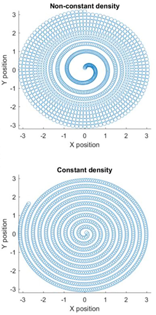
Figure 1: Non-constant density scan vs constant density pattern
We created a constant density scan pattern in MATLAB and saved the X and Y coordinates to an SD card in .CSV format. Using the Moku:Lab Arbitrary Waveform Generator, we then imported the file and generated these X and Y position commands onto output Channel 1 and Channel 2 (Figure 2). Note using an SD card is not the only way to import the desired waveforms – uploading the files via Dropbox, email, or the iPad’s My Files can also be used [2].
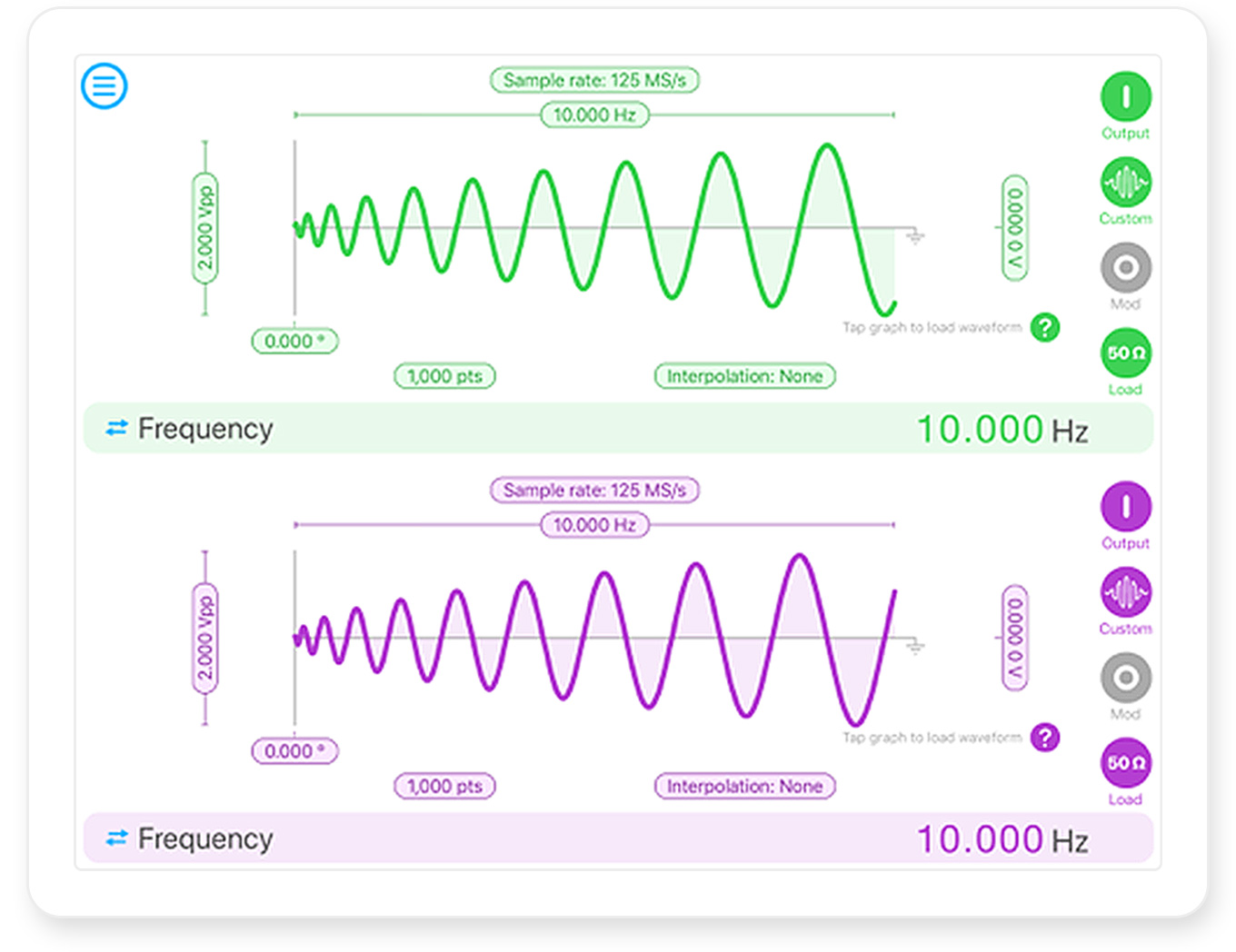
Figure 2: Configuring the output channels to drive the X and Y position coordinates using the Moku:Lab Arbitrary Waveform Generator

Figure 3: The Moku:Lab Oscilloscope in XY mode, confirming the output of the spiral scan pattern
To confirm that the Arbitrary Waveform Generator was correctly generating the patterns at 10 Hz and 2 V, we used a second Moku:Lab running an oscilloscope in XY mode (Figure 3).
Demonstration of laser spiral scan
Acquisition scan patterns are an integral part of establishing long range free-space laser links. To demonstrate our spiral scan pattern as a potential link acquisition platform, we set up a simple beam steering system whereby Moku:Lab steered the beam using the Arbitrary Waveform Generator.
For beam steering, we used a Newport FSM-300 fast steering mirror. It can be supplied with analog ±10 V signals to control the tip and tilt of the mirror in the X and Y planes, respectively. Since the output range of Moku:Lab is ±1 V, we used two amplifiers on each channel to increase the amplitude of the drive signal (Figure 4). We did this so that we could drive the steering mirror at the maximum steering range to maximize our scan area.
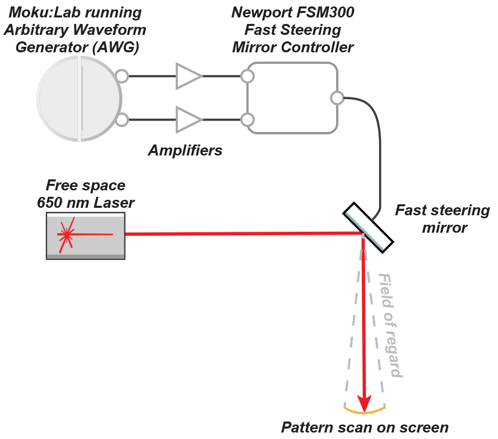
Figure 4: Diagram of setup showing Moku:Lab generating the X and Y scan patterns for the fast steering mirror
We set up the components on an optical bench in the lab (Figure 5) and positioned a projector screen about 5 m away from the steering mirror.
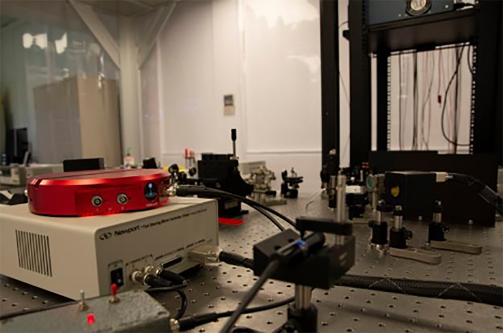
Figure 5: The experimental setup
The fast steering mirror has an analog bandwidth up to about 2 kHz. Note that the spiral scan pattern that we generated does not start and finish at the same point – there is a noticeable straight line that links the inside of the spiral to the outside. This sharp change of direction results in significantly higher frequency harmonics than the spiral scan frequency. When we ran the scan at 3 Hz or greater, the straight line began to bend as the higher harmonics required for the sharp turns were out of the bandwidth of the steering mirror.
We captured a photo of the scan pattern at 1 Hz with a long exposure photo shot on a DSLR camera (Figure 6).
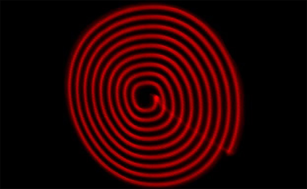
Figure 6: The scan pattern as seen on the projector screen
Conclusion
Acquisition scan patterns are an important aspect of setting up a long range, free space laser link such as that in GRACE Follow-On. A constant density scan is required over the entire region of interrogation, which usually results in an arbitrary waveform pattern being used. We created a constant density spiral scan pattern in MATLAB, then imported it into the Moku:Lab Arbitrary Waveform Generator by SD card. We then used this to drive a fast steering mirror that steered a visible red laser onto a projector screen using the spiral scan pattern. This demonstrated the Moku:Lab device’s capability to produce arbitrary complex waveforms that can be used for acquisition scan patterns for free space laser links
Further reading
[1] Danielle M. R. Wuchenich, Christoph Mahrdt, Benjamin S. Sheard, Samuel P. Francis, Robert E. Spero, John Miller, Conor M. Mow-Lowry, Robert L. Ward, William M. Klipstein, Gerhard Heinzel, Karsten Danzmann, David E. McClelland, and Daniel A. Shaddock, “Laser link acquisition demonstration for the GRACE Follow-On mission,” Opt. Express 22, 11351-11366 (2014)
[2] Moku:Lab Arbitrary Waveform Generator user manual https://liquidinstruments.com/arbitrary-waveform-generator/