


This recap and Q+A complement our webinar, entitled “High-performance PDH locking with Reconfigurable Instrumentation,” which we co-hosted with Photonics Media on June 18, 2024. A Chinese version of the webinar was hosted by Aunion Tech on June 21st. If you weren’t able to attend either live, register now for on-demand access.
In addition to a webinar summary, we’re providing in-depth answers to select audience questions below.
Webinar recap
This webinar consisted of three segments. In the first segment, we discussed the motivations and methods for stabilizing a laser, as well as its applications. We also shared different techniques for locking a laser to an optical reference cavity, including side-of-fringe locking, dither locking, and Pound-Drever-Hall (PDH) locking, with the relative advantages and disadvantages of each.
In the second segment we presented a deep pedagogical dive into the physics of laser locking. We explored signal processing topics such as phase modulation, I/Q signals, and cavity dynamics, alongside graphical aids to help visualize the processes of PDH error signal generation.
In the final segment, we performed a live demonstration of the Moku Laser Lock Box as an all-in-one laser stabilization tool. We emulated a laser locking setup using Multi-instrument Mode entirely on Moku:Pro, with a Waveform Generator acting as a frequency source and the Digital Filter Box as the reference cavity. We established a lock to our pseudo-cavity using the PDH method.
Questions from the audience
Do I need an additional reference cavity and electro-optic modulator (EOM) to use with this instrument?
Yes. In a PDH locking setup, the Moku Laser Lock Box replaces the functionality of the Lock-in Amplifier, low-pass filter, PID controller, and modulation source. Since the exact configuration and requirements for the locking can vary greatly, the user needs to supply their own EOM, reference cavity, and photodiodes.
Can Moku be used for Hänsch-Couillaud locking?
While it was not covered in the webinar, the Hänsch-Couillaud method is another laser locking technique. It involves generating a linearly polarized laser beam and sending it through a polarizer placed inside the reference cavity. After exiting the cavity, the reflected beam passed through a beam splitter to one of two photodetectors. The error signal is then simply the difference between the photocurrents of these detectors.
Since there is no frequency modulation, EOM, or demodulation required in this case, this portion of the Laser Lock Box’s functionality is not needed. From the main screen of the Laser Lock Box, users can set the demodulation source to “None,” and Input A will be the error signal itself, with the fast and slow PID parameters set as normal.
The Moku PID controller can also perform this locking method, acting as the differential amplifier via its built-in control matrix in addition to the ability to generate a feedback signal.
Can the Moku support the quadrature demodulation during the PDH process?
The Laser Lock Box currently offers single-phase demodulation for the error signal. The Moku Lock-in Amplifier, on the other hand, offers the option for dual phase demodulation as well as the choice between rectangular (X/Y) and polar (R/Θ) coordinates. If you require the use of IQ demodulation for your laser locking needs, we recommend using the Moku Lock-in Amplifier, alongside the embedded PID controller for generation of the feedback signal, as seen in Fig 1.
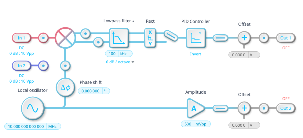
Figure 1. Moku lock-in amplifier instrument, showing the X and Y coordinates along with embedded PID controller on the instrument output.
What digital filtering options are available?
The Moku Laser Lock Box has an embedded, digital low-pass filter in the signal processing chain, following immediately after demodulation to remove the high frequency components. The corner frequency of this filter can be set arbitrarily. If you need to further filter your input or output signals, the Laser Lock Box can be used in conjunction with the Digital Filter Box, as seen in Fig. 2. Included in the Digital Filter Box are options for low-pass, high-pass, and bandpass filters of 8 different types (Gaussian, Butterworth, etc.), or your own custom filter function. Users can also add a voltage offset or gain to signals in the DSP chain.
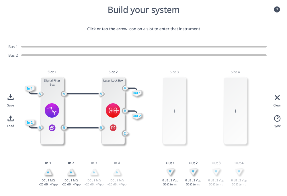
Figure 2. The Moku Digital Filter Box can complement the Laser Lock Box by filtering the input signal from the photodiodes.
Is there an established process for optimizing the PID parameters?
As the PID parameters needed for different experiments can vary greatly, there is not a standard process for optimizing PID parameters. Some algorithmic processes, like the Ziegler Nichols method, exist to help with automation. In general, it is desirable to set the gain as high as possible at frequencies where there is noise (usually low frequencies) and as low as possible where sensing noise dominates (usually at higher frequencies). The unity gain will then be at intermediate frequencies, which is where one will need to carefully address the stability of the system. If you need assistance optimizing the Moku PID controller for your, please check out our Knowledge Base.
What happens if the sidebands fall within the linewidth of the cavity? Does PDH still work?
During PDH locking, a laser beam with carrier frequency ω0 is typically phase modulated by an EOM, producing sidebands at frequencies ω0 ± Ω. The cavity itself has its own linewidth, defined as the full-width half-maximum (FWHM) of the cavity’s resonant mode, Δω.
It is indeed possible to lock a laser using a modulation frequency that is slower than the cavity bandwidth (i.e., Ω.<<Δω). This technique is sometimes called dither locking, as the laser frequency is essentially being adiabatically swept within the cavity. The results of a typical dither locking error signal are seen in Fig. 3. While this technique still produces an asymmetrical error signal that can be used to lock the laser, it comes at the cost of speed. As mentioned, the modulation frequency must be slow, which limits how fast the PID controller can respond to the signal.
For optimal control using narrow cavities, it is better to modulate the laser frequency at a rate much higher than the cavity linewidth, Ω.>>Δω. As seen in Fig. 3, the error signal has a sharp linear behavior near zero, meaning that the PID controller can respond much more quickly to any drift of the laser frequency.
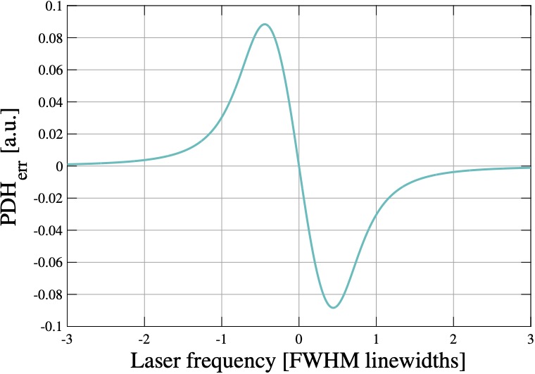
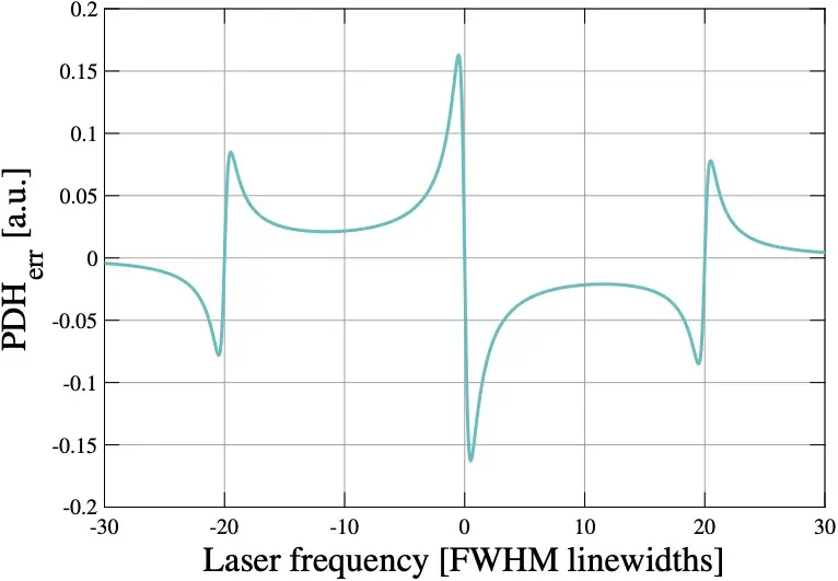
Figure 3. PDH error signal produced with the sidebands inside (top) and outside (bottom) of the cavity linewidth. When the cavity linewidth is much smaller than the modulation frequency, a steep slope is produced near the zero crossings, allowing for precise and rapid PID control.
How would you recommend analyzing the noise present in the output signal/feedback signal?
The Moku Laser Lock Box offers a built-in PID Controller that can output both a fast and slow control signal. There are two ways that these signals can be analyzed. The first is to use the embedded Oscilloscope by selecting the probe points near Output A and Output B of the Laser Lock Box configuration screen. If needed, use the Math channel of the Oscilloscope to perform an FFT analysis as shown in Fig. 4. This is a quick and efficient way to check your feedback signals before they are passed to your laser.
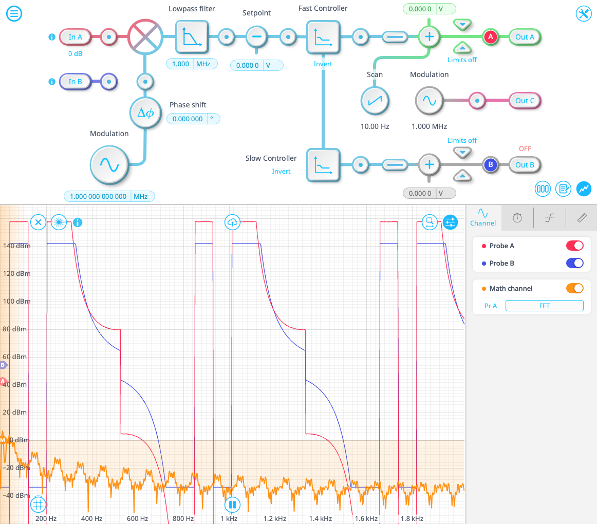
Figure 4. Fast and slow PID control signals as viewed on the embedded Oscilloscope. The Math channel is enabled for frequency-domain analysis.
If you need a more rigorous analysis of your feedback signals, you can use Multi-instrument Mode and run the Laser Lock Box alongside the Moku Spectrum Analyzer. As seen in Fig.5, the outputs of the Laser Lock Box can also be diverted to the input of the Spectrum Analyzer, allowing you to operate your feedback loop while simultaneously monitoring the signal on the Spectrum Analyzer.
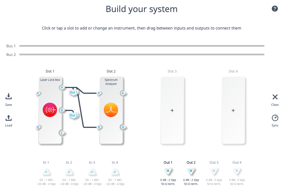
Figure 5. Multi-instrument Mode setup for a Laser Lock Box and Spectrum Analyzer. The output channels of the Laser Lock Box, corresponding to the fast and slow PID control signals, are sent to the digital-to-analog converters on the Moku front panel (Output 1 and Output 2). Simultaneously, the signals are passed to the Spectrum Analyzer for frequency domain monitoring.
Is it possible to code in and use one’s own instrument within the Moku?
If you’re interested in running custom tools on your Moku device, read about Moku Cloud Compile. With Moku Cloud Compile, you can write your own FPGA code in VDHL and compile it on our website. After the code compiles, you can download a bitstream to deploy to your device. You can also find our example tools, including a boxcar averager and a moving-average filter.
Thank you for viewing our webinar. We look forward to seeing you again!For more insightful demonstrations, check out our webinar library for on-demand viewing.
More questions?
Get answers to FAQs in our Knowledge Base
If you have a question about a device feature or instrument function, check out our extensive Knowledge Base to find the answers you’re looking for. You can also quickly see popular articles and refine your search by product or topic.
Join our User Forum to stay connected
Want to request a new feature? Have a support tip to share? From use case examples to new feature announcements and more, the User Forum is your one-stop shop for product updates, as well as connection to Liquid Instruments and our global user community.