






Introduction
The digital phase-locked loop (PLL) is a powerful technique used in Moku devices to continuously track the phase of an input signal with zero dead time. This technique is used in Moku’s Lock-in Amplifier and Laser Lock Box to generate a phase-locked demodulation signal, and in the Phasemeter to measure the real-time phase, frequency, and amplitude of a signal. Detailed working principles of Moku’s PLL can be found in this application note. Moku’s digital PLL functionality was further enhanced in the release 2.5 software update. Moku can now generate a phase-locked sine wave not only at the same frequency as the input signal, but also at a multiple or division of the input signal frequency. In this white paper, we will demonstrate some of the use cases this feature can enable.
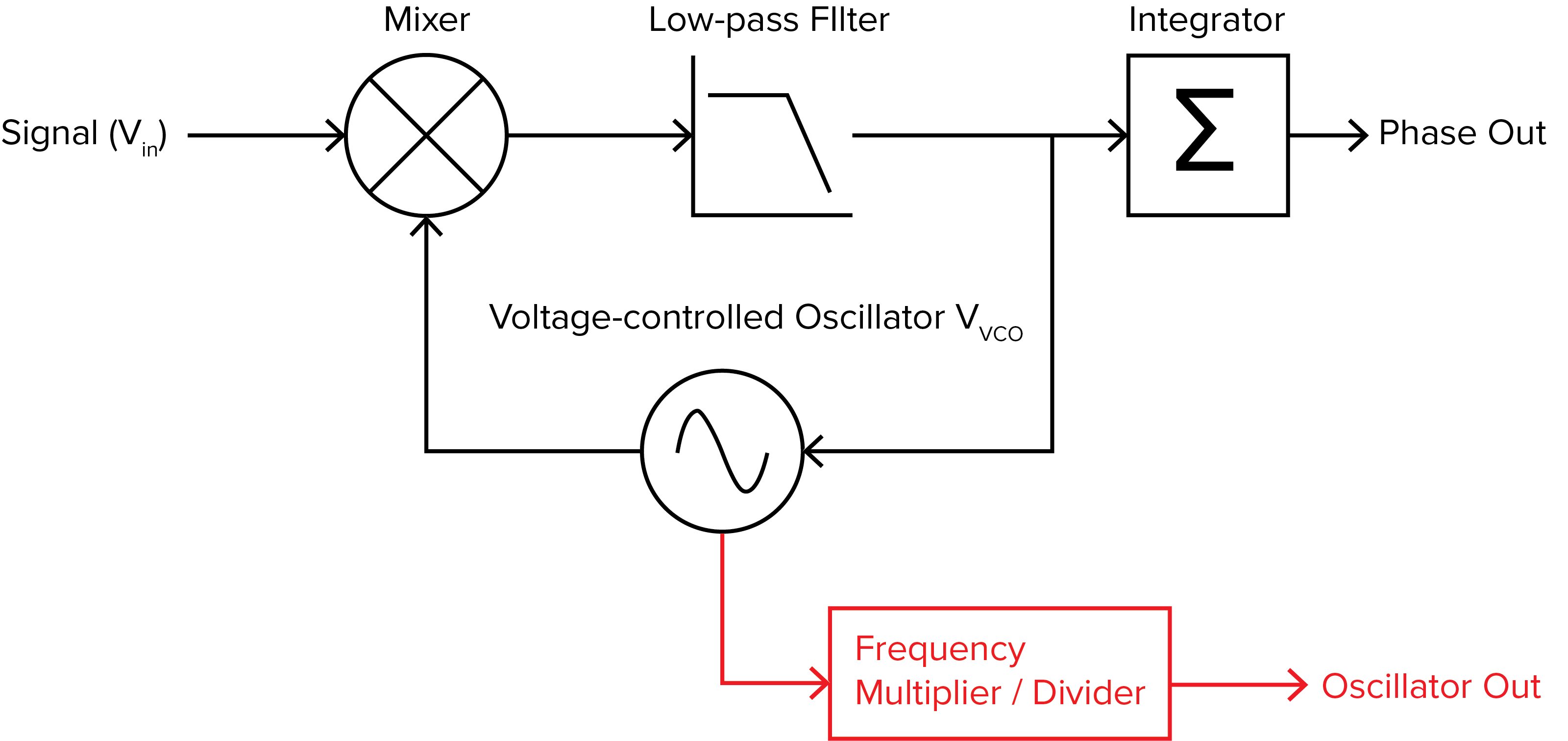
Figure 1: A simplified block diagram of Moku’s PLL. The frequency multiplier and divider feature is routed out of Moku’s voltage-controlled oscillator.
Harmonic demodulation for the Lock-in Amplifier
The PLL is an essential component of Moku’s Lock-in Amplifier, used to lock to an external reference and generate the reference for dual-phase demodulation. With the new frequency multiplier and divider feature, the Lock-in Amplifier can now demodulate the input signal at one or more harmonics or frequency divisions of an external reference simultaneously. To demonstrate this, two Lock-in Amplifiers were deployed in Multi-Instrument Mode on a Moku:Pro, as shown in Figure 2(a). The first Lock-in Amplifier was set to demodulate at the fundamental frequency of the reference signal, while the second was set to demodulate at the second harmonic of the reference signal, as shown in Figure 2(b). The measured amplitudes (R) were routed to the Oscilloscope for comparison. A Moku:Lab was used to generated a 10 MHz square wave as the signal of interest, which is connected to Input 1 of the Moku:Pro; a 10 MHz sine wave was also generated as the reference signal, which is connected to Input 2 of the Moku:Pro.
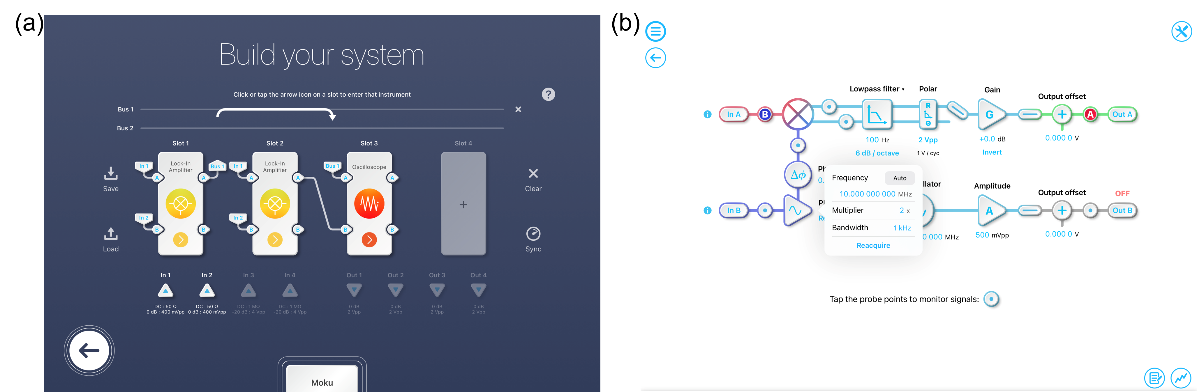
Figure 2: (a) Multi-Instrument Mode setup for demonstrating multi-harmonic demodulation. (b) PLL settings for the second Lock-in Amplifier to demodulate at the second harmonic. Square waves with 50% duty cycle consist of only odd harmonics. Therefore, in Figure 3a, the first Lock-in amplifier measured a strong power at the fundamental frequency (red trace), while the second Lock-in Amplifier detected almost no power at the second harmonic (blue trace). However, if the duty cycle is increased, the second harmonic will also start to increase. This is observed in Figure 3b, where an increase in duty cycle led to increased power in the second harmonic and a corresponding decrease in power in the fundamental.
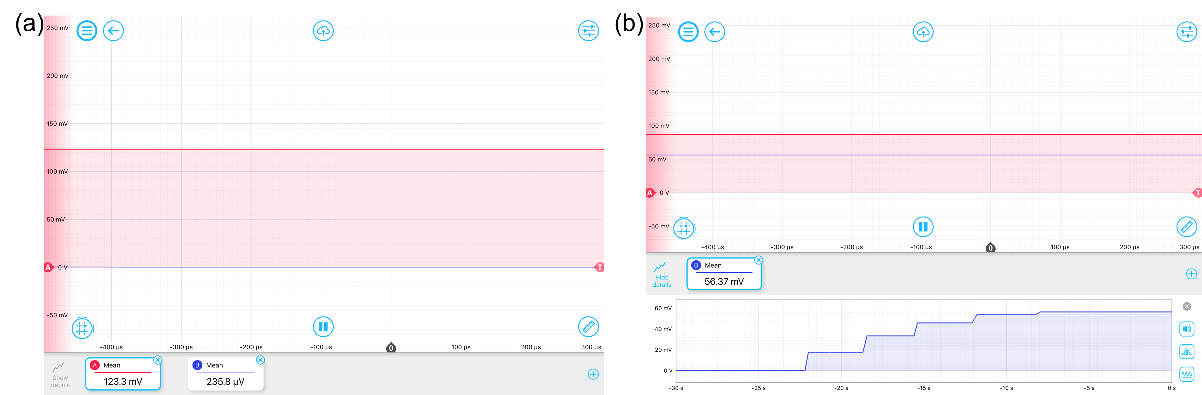
Figure 3: (a) Measured amplitude at the fundamental frequency (red) and the second harmonic (blue) by the two Lock-in Amplifiers at 50% duty cycle. (b) Measured amplitude at the second harmonic increased with increasing duty cycle.
Generating Phase-locked Signals
Harmonics and sub-harmonics of a reference signal can now be easily generated. Using the Phasemeter, you can lock to the fundamental frequency of the input signal and generate phase-locked sine waves at up to 250x multiple of this fundamental with 0.125x precision or divide it down to 0.125x. This can be used to generate the local oscillator signal for heterodyne detections at a particular harmonic or create phase synchronization between multiple clock domains. To demonstrate this feature, we will use a Phasemeter to phase lock to a frequency modulated signal and then generate a phase-locked signal at 64x the carrier frequency. The Multi-Instrument Mode setup is shown in Figure 4a: a Waveform Generator is deployed in Slot 1 to generate the original FM signal (1 MHz center frequency with a 1 kHz modulation depth and 100 mHz modulation rate); the Phasemeter in Slot 2 is phase-locked on to the original FM signal and output a phase-locked signal at 64x the frequency; an Oscilloscope was deployed in Slot 3 for signal monitoring and comparison.
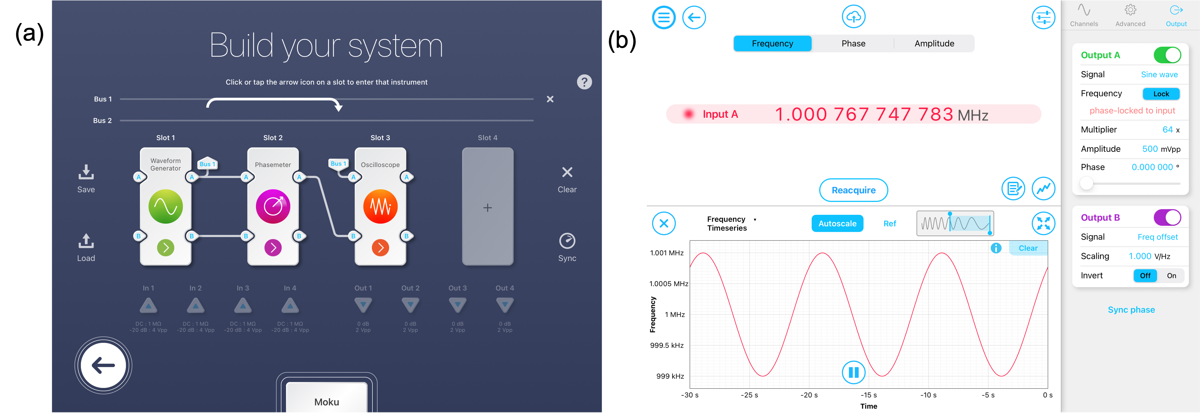
Figure 4: (a) Multi-Instrument Mode configuration for generating phase-locked signal with Phasemeter frequency multiplier. (b) Settings for Phasemeter in Slot 2. Figure 5 shows a comparison between the original FM signal and the frequency-multiplied signal. Channel A shows the signal from the Waveform Generator at 1 MHz, while Channel B is at 64 MHz. As the Phasemeter was set to lock on to the center frequency of the FM signal, only the center frequency was multiplied 64x, preserving the 100 mHz modulation frequency.
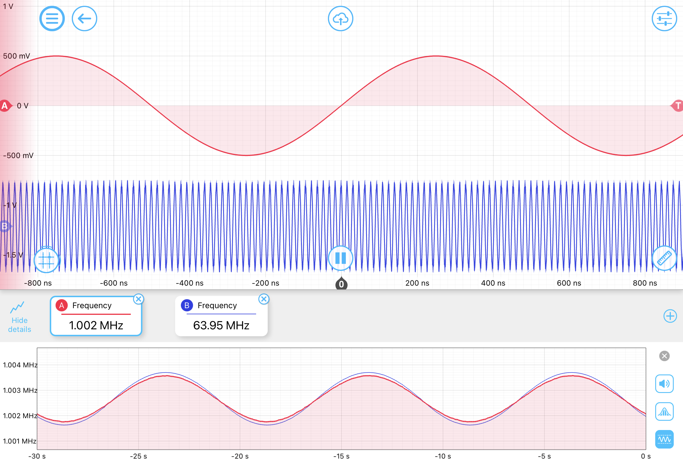
Figure 5: Oscilloscope measured signals, where the red trace shows the original FM signal at 1 MHz and blue trace shows the phase-locked FM signal at 64 MHz. As the two signals are phase-locked, they show the same frequency modulation.
Conclusion
The addition of frequency multiplier and divider to Moku’s PLL further enhanced Moku Lock-in Amplifier, Laser Lock Box, and Phasemeter. This feature unlocks the capability to detect and output signals at up to 250 times or down to 0.125 times the input frequency. You can now use Moku in a wider range of real-time closed-loop control applications, such as laser locking to side bands or higher harmonics. Update your Moku app now to gain access to the latest features. To get started with implementing PLLs, check out our quick-start checklist.