






Updated October 1st, 2026
This technical paper provides an overview of the implementation and verification of a phase locked loop (PLL) using Multi-Instrument Mode on Moku:Pro hardware. The reader will gain an understanding of the features of Moku Pro and its user interface together with Moku’s powerful ability to test and verify the performance of a widely implemented system, the PLL.
Moku:Pro is a reconfigurable FPGA-based hardware platform with a suite of over 15 software-defined instruments. Its reconfigurable nature allows a single Moku device to consolidate functionality and operate seamlessly among other instruments in any test setup. As will be seen, instruments can be interconnected and signals passed between them entirely in the digital domain within the FPGA. This consolidation enables high data rates with ultra-low latency between instruments, as well as shared internal clock for perfect time synchronization.
In the next sections we show how a PLL operates and make use of Multi-Instrument Mode to build a PLL entirely within a Moku:Pro device.
Principles of a phase-locked loop
A phase-locked loop is a system that tracks the phase of an incoming signal by comparing it to a reference. It then uses the resulting error to control the frequency of an output signal, effectively locking the output and input together. This is useful across the spectrum of applications, from research and development to design and prototyping to testing, For example, a PLL is a fundamental component of radio receivers and other telecommunications, providing stable clocks for computers, synchronizing clocks, or generating frequencies at multiples of the source signal (frequency synthesis).
As seen in Figure 1 below, the most basic PLL consists of a phase detector followed by a low-pass filter and a voltage controlled oscillator (VCO). A VCO provides a frequency output proportional to its input voltage.
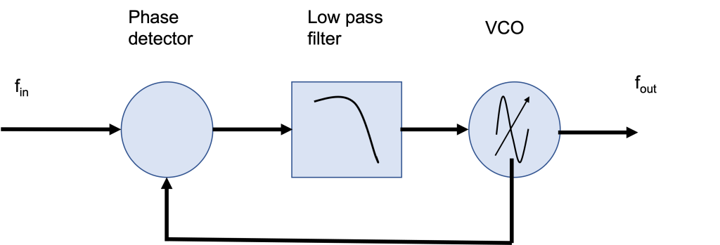
The phase detector (PD) receives two inputs: the external signal (labeled \(f_{in}\)), and the reference or local oscillator. The PD outputs a voltage that is dependent on the phase difference of the input clocks, which in turn drives the VCO. There are different possible implementations of the PD. For example, an analog frequency mixer (or demodulator) can be used. This has the disadvantage of generating unwanted frequency spurs or harmonics and requires a low-pass filter, which limits the lock time or capture range. An alternative PD implementation uses digitally implemented phase-frequency detector, such as the one used in the Moku Phasemeter instrument.
Implementing a PLL with Moku
Below, we discuss each component that makes up the PLL and how to implement it on the Moku hardware.
Multi-instrument configuration
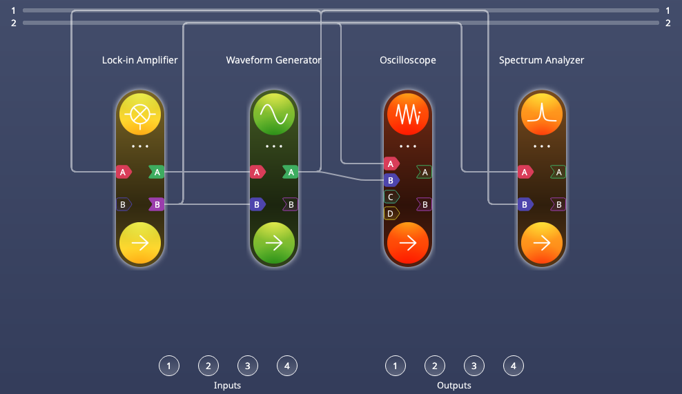
We first configure Multi-Instrument Mode, seen in Figure 2 below. Slot 1 contains the Lock-in Amplifier, which functions as the phase detector. Slot 2 is occupied by the Waveform Generator, which uses its frequency modulation capability to act as the VCO. The output of the VCO is driven to the internal bus and looped back to Input A of the Lock-in Amplifier (PD).
It is helpful to be able to observe the PLL behavior in both time and frequency domains so we have deployed the Oscilloscope in Slot 3 and the Spectrum Analyzer in Slot 4. Both are set up to observe bus 1 (reference LO) and bus 2 (VCO output). All four instruments operate simultaneously and independently. We use this setup to examine the PLL behavior, but in a more realistic application the VCO would typically supply the LO and lock to a signal supplied externally and fed to Input A of the LIA.
Phase detector
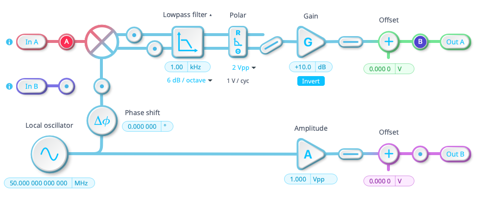
A typical lock-in amplifier (LIA) has a demodulation stage followed by a low-pass filter. Since the Moku Lock-In Amplifier can also convert the X-Y quadrature output to magnitude and phase (r-Φ), we can use this instrument as the phase detector. Figure 3 shows the Moku Lock-in Amplifier user interface with the local oscillator set to 50 MHz, the demodulator followed by a lowpass filter (1 kHz), rectangular to polar conversion, and finally gain, inversion, and offset functions. The phase output of the polar conversion is inverted and fed to Out A and will form our phase measurement.
VCO
The VCO is implemented on Moku:Pro using the Waveform Generator instrument. The Moku Waveform Generator can modulate the output from a variety of sources. For example, the modulation source can be another waveform generator, an internal source, or an input to the instrument. Figure 4 shows the Waveform Generator user interface. To implement the VCO the Waveform Generator is configured to generate a frequency modulated (FM) sine wave, with source of modulation set to Input A, The modulation depth is set at +/- 50 kHz/V, which determines the maximum capture range.
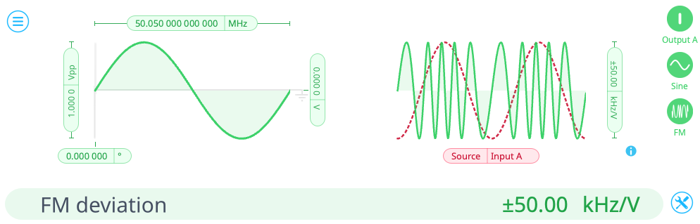
The Multi-Instrument Mode inter-instrument busses have a range of 2 Vpp, so the maximum FM deviation is +/- 50 kHz. The carrier frequency is set to 50.05 MHz, a deviation 50 kHz from the lock-in’s local oscillator of 50 MHz, and so will require the full FM deviation range.
PLL operation
At initial setup, the Lock-in Amplifier is configured with its Output A disabled (represented by the open switch between the gain and offset stages). The means the loop is not closed and the Waveform Generator will output its FM signal at 50.05 MHz. Figure 5 shows the user interface of the Lock-in Amplifier in slot 1 with the embedded oscilloscope showing the LO at 50 MHz and the incoming signal on input A at 50.05 MHz. These signals are not locked and the incoming phase is continuously rolling past the reference LO.
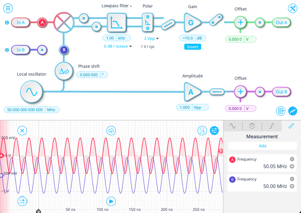
Figure 6 below shows the user interface of the Oscilloscope in Slot3, which confirms the unlocked status of the PLL. The frequencies of the VCO (Channel B) and reference (Channel A) are separated by 50 kHz, with the phase difference fluctuating +/- 180 degrees.
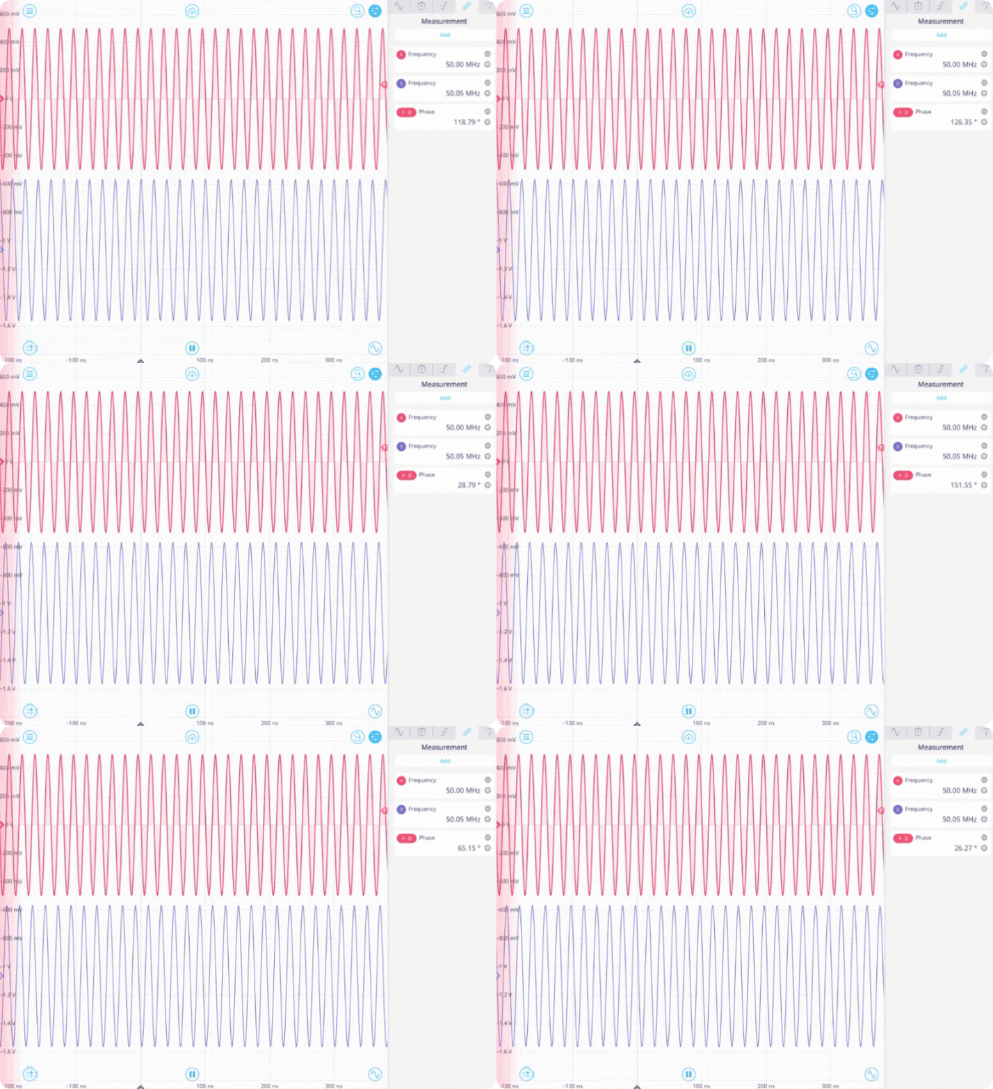
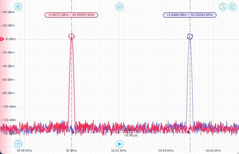
Figure 7 shows the Spectrum Analyzer in Slot 4 in the same unlocked PLL situation. We see the LO on channel A at 50.000 MHz and the VCO output at 50.051 MHz, a steady and fixed frequency offset
Locking the PLL
Now we enable the Lock-in Amplifier output by closing the loop seen in Figure 5. The Lock-in Amplifier output is now driving an error signal representing the instantaneous phase error between the LO and the VCO output. The Waveform Generator (VCO) responds and the loop locks while the output tracks the LO.
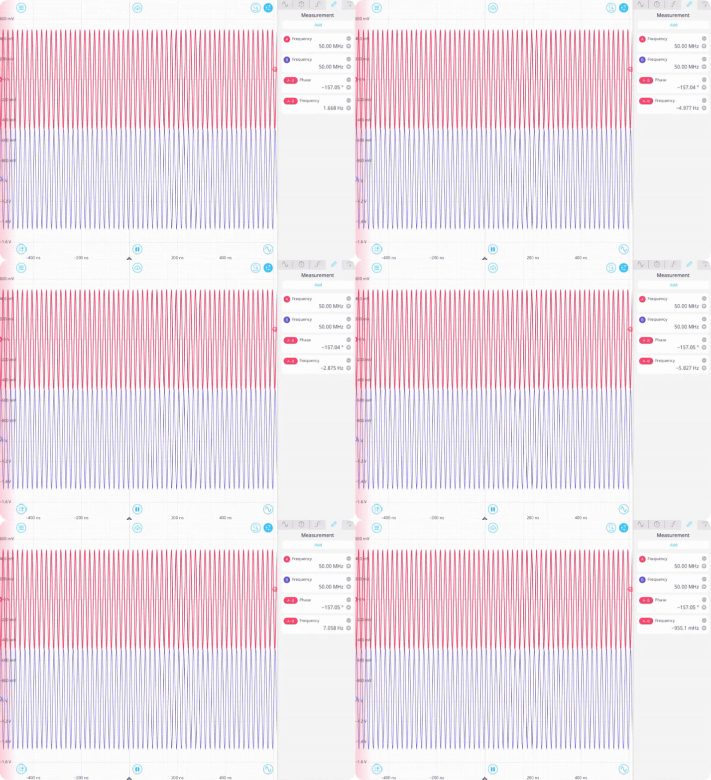
Figure 9 shows the Oscilloscope in Slot 3 with two locked sine waves and a steady phase difference between the LO and VCO of mean ~157 degrees a fluctuating frequency difference on the order of a few Hz. Depending on the application, it is worth experimenting with various modulation depths (high FM deviation per volt), which will alter the tracking bandwidth. The data confirms this, and that narrower locking bandwidths improves the precision of he lock.
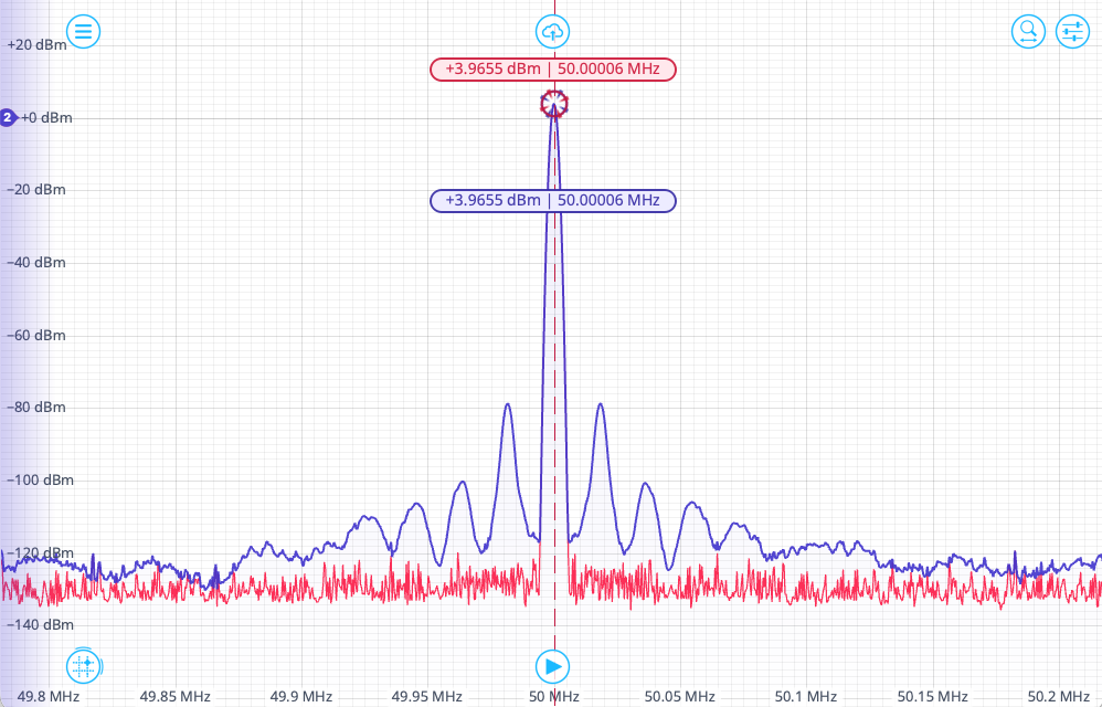
In Figure 11 the Spectrum Analyzer in Slot 4 shows the VCO and LO are now locked at 50.00006 MHz, with some additional sidebands on the VCO signal representing the jitter in the signal as it is continuously being tuned.
Conclusion
In this technical note we have implemented a PLL on Moku hardware. We locked a VCO (using the Moku Waveform Generator) to the Lock-in Amplifier’s internal reference. While this is a demonstration of the principles of PLLs and the intuitive Moku:Pro user interface, a typical application would involve locking to an external signal (sampled via Moku:Pro’s ADCs) of unknown frequency such as a radio carrier wave. The locked signal could then be driven externally to the Moku:Pro analog output
The intuitive graphical user interface allowed us to perform this experiment in a few minutes and observe the fast lock time and lock range (+/- 50kHz). We have observed the PLL locking in both time and frequency domains using the Oscilloscope and Spectrum Analyzer instruments.
There are numerous applications that are enabled by such a flexible test platform. While this note and example operated entirely within one Moku:Pro, either the PD or VCO element could be an external system under test. Further, the example could be used to evaluate a design proposal, using Moku hardware to evaluate design parameters before committing to hardware.
Contact our team to discuss your application.
Have questions or want a printable version?
Please contact us at support@liquidinstruments.com