






The Moku Neural Network is the only FPGA-based neural network integrated into a full suite of test and measurement instruments. This instrument allows the user to run real-time, powerful machine learning algorithms in line with your experimental setups using the Moku:Pro. You can build and train models using Python, then deploy to your test systems using Moku:Pro to achieve low-latency inference and react quickly to changing experimental conditions. In the following example, we explore the use of an autoencoder type of neural network structure to de-noise pulsed waveforms. We will then apply a matched filter to non-noisy, noisy, and de-noised data to highlight the effectiveness of the Neural Network instrument in a pulsed waveform scenario compared to a matched filter.
Using a matched filter for pulse detection
Pulsed waveforms are widely used in various applications, with radar systems being a prominent example. In the simplest configuration, a pulsed radar emits short, powerful pulses of electromagnetic energy at a constant frequency, then enters a “listening” mode to detect echoes from targets. During this listening period, the radar system is essentially silent, waiting for the return signal (echo) from objects in the environment. One of the key challenges in pulsed radar systems arises from the attenuation of the received signal. As the pulse travels from the radar to the target and back, it experiences spreading losses, which cause the signal to weaken with distance. The degree of attenuation is proportional to the square of the distance between the radar and the target, a phenomenon often referred to as free-space path loss. Intentional (e.g. in the form of jamming) or unintentional noise can often further challenge the radar receiver and make it difficult to distinguish the presence of a pulse in the received waveform. In order to aid with pulse detection, a matched filter is commonly employed to detect the pulse presence and timing in a noisy waveform. A matched filter is a time-reversed copy of the transmitted pulse that is convolved with the received signal. The effectiveness of a matched filter is highly dependent on both the pulse and noise characteristics. While a matched filter will aid with pulse discovery in the received waveform, the performance generally improves with an increased Signal-to-Noise Ratio (SNR). There are other techniques employed by advanced radar systems such as pulse compression, frequency diversity, and many other signal processing strategies that will be demonstrated in future white-papers.
Simulating radar data and de-noising with the Neural Network instrument
Materials and hardware configuration
- Moku waveform generator for pulse generation
- Moku:Pro to apply the Neural Network to received data
Pulse parameters
- Carrier Frequency – 2 kHz
- Pulse Width – 5 ms
- Pulse Repetition Frequency – 10 Hz
Users can generate the pulsed waveform with a single Moku:Go running in single-instrument mode. In order to generate a simple pulsed waveform, generate a sine wave on channel 1 that is Amplitude Modulated by channel 2. On channel 2, we can create the modulation source by generating a pulse waveform with the desired frequency and pulse width, seen in Figure 1.
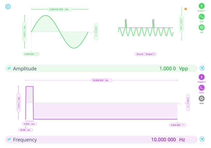
Figure 1: Moku:Go Waveform Generator pulsed signal parameters to simulate a pulsed radar signalConnect this pulsed waveform via Output 1 on Moku:Go to Input 1 on Moku:Pro. Configure Moku:Pro in Multi-Instrument Mode (Figure 2) with all four instrument slots utilized.
- Slot 1 – Waveform Generator to generate noise
- Slot 2 – PID Controller to use control matrix to combine noise with pulsed signal
- Slot 3 – Neural Network with previously built autoencoder *.linn file
- Slot 4 – Data Logger used to store 0.2s snapshots of data
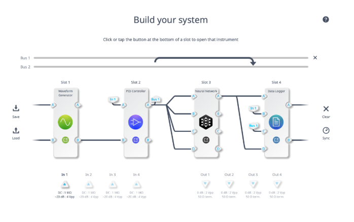
Figure 2: Moku:Pro Multi-Instrument Mode configurationFor purposes of this experiment, we use the PID Controller only to combine the noise with the received signal from the Moku:Go. The PID Controller has an input control matrix which allows us to scale and combine signals from two separate inputs. After applying the appropriate scaling from the control matrix, the remainder of the PID Controller acts as a pass through for the noisy pulse. Slot 3 contains an autoencoder neural network configuration. An autoencoder is a type of neural network structure that aims to learn efficiently compressed representations of input dataset. It achieves this with a network architecture that tapers to some smaller latent space representation, before expanding back to the input size. An autoencoder can generally be thought of as consisting of two networks: the encoder and decoder networks, respectively. The encoder is responsible for learning the compressed representation of the input data while the decoder is responsible for reconstructing the input from the latent variable representation. It’s important to note that training data used for this autoencoder did not consist of the pulsed waveform – only random walk signals. Despite this fact, the neural network was still successful at accurate pulse identification at significantly reduced levels of SNR.
Results
With sufficient SNR, matched filters are excellent tools to identify precise location of a known pulse type within a signal. As shown below, the signal is tough to identify visually in the presence of noise, but the matched filter can effectively pull this signal out of the noise. However, the signal processed in real time with the Neural Network instrument further improves the performance of the matched filter and would allow for a lower detection threshold. The vertical hashed green lines in Figure 3 indicate the expected peak of correlation. The horizontal hashed red lines indicate an arbitrary detection threshold at 50% of peak correlation within the window.
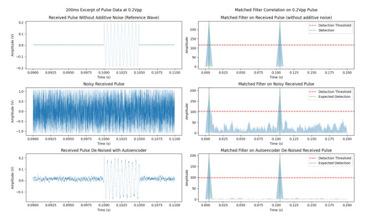
Figure 3: Comparison of radar pulse detection results using a Neural Network based Autoencoder (left) and a matched filter (right)As SNR decreases, we start to see false detections with the chosen threshold on the noisy signal. Situations like this would be challenging for anyone trying to interpret the received radar data, as it would be impossible to ascertain a true pulse return from Ωnoise. However, the de-noised signal through the Neural Network allows for flawless identification of the pulses and would still allow for a lower detection threshold, as shown in Figure 4.
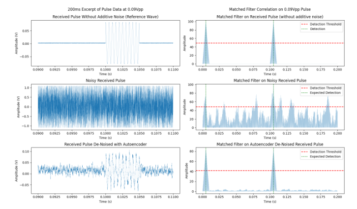
Figure 4: Comparison of radar pulse detection with a 0.09 Vpp input signal using an autoencoder (left) and matched filter (right)With an even further reduction in SNR shown in Figure 5, the matched filter’s ability to detect the pulses in the noisy signal is completely lost. However, the signal de-noised in real time through the Neural Network continues to perform well.
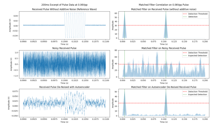
Figure 5: Comparison of radar pulse detection of a 0.06 Vpp input signal using an autoencoder (left) and matched filter (right)Eventually, a further reduction in SNR will begin to limit the performance of the de-noised signal with the Neural Network. However, this de-noising technique does present significant improvement in performance over the matched filter alone. In Figure 6, we start to see false detections, but the true detections are still accurate.
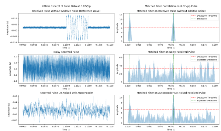
Figure 6: Comparison of radar pulse detection on a 0.02 Vpp inputs signal using an autoencoder (left) and a matched filter (right)
Conclusion
Moku devices allow for a convenient investigation into the challenges in pulse identification in the presence of noise. Additionally, a neural network was applied in the Moku hardware to de-noise the data in real-time. An interesting aspect of this neural network configuration is that the training data did not consist of the pulsed waveform. Despite this fact, the neural network was still successful at allowing accurate pulse identification at significantly reduced levels of SNR.
Questions?
Get answers to FAQs in our Knowledge Base
If you have a question about a device feature or instrument function, check out our extensive Knowledge Base to find the answers you’re looking for. You can also quickly see popular articles and refine your search by product or topic.
Join our User Forum to stay connected
Want to request a new feature? Have a support tip to share? From use case examples to new feature announcements and more, the User Forum is your one-stop shop for product updates, as well as connection to Liquid Instruments and our global user community.