Analog signals can be precisely delayed by employing delay lines. In digital systems that are quantized in time, a delay of an integer number of samples can be implemented trivially but implementing fractional delays is more challenging. Fortunately, the advanced FIR Filter Builder developed by Liquid Instruments serves as a reliable and powerful tool for implementing fractional delays on arbitrary signals.
The action of an FIR filter is that of convolution:

where n is the sample index, * is the convolution operator, y is the output of the filter, x is the input and h is the filter’s impulse response. A useful property of convolution is:

so that to obtain a delayed filter output we may simply apply a delayed filter to the original input signal. For example, a trivial unity gain, all-pass filter could be written as:

where our filter impulse response is h[n]=δ[n]. To implement a one-sample delay one could construct the following filter:

Note how the delayed filter impulse response ([0 1] rather than [1]) leads to a delayed output. This method can easily produce integer-sample delays, but fractional delays are still unobtainable (one cannot implement e.g. δ[0.5]).
Fractional delays
The frequency response of a filter is the Fourier transform of its impulse response. To implement fractional delays without changing the magnitude of the signal we need a filter kernel whose Fourier transform has a flat, unity-gain frequency response up to Nyquist frequency and then a sharp cut-off, rolling off to zero for higher frequencies, ideally like a rectangle. If we know the analytical form of such a function then it can be evaluated at arbitrary delays. Noting that the sinc function (sine cardinal) is the Fourier transform of the rectangle function, the sinc function will prove a useful prototype impulse response for implementing fractional delays. By adding an appropriate offset in the argument of the sinc filter, its delay may be arbitrarily controlled.

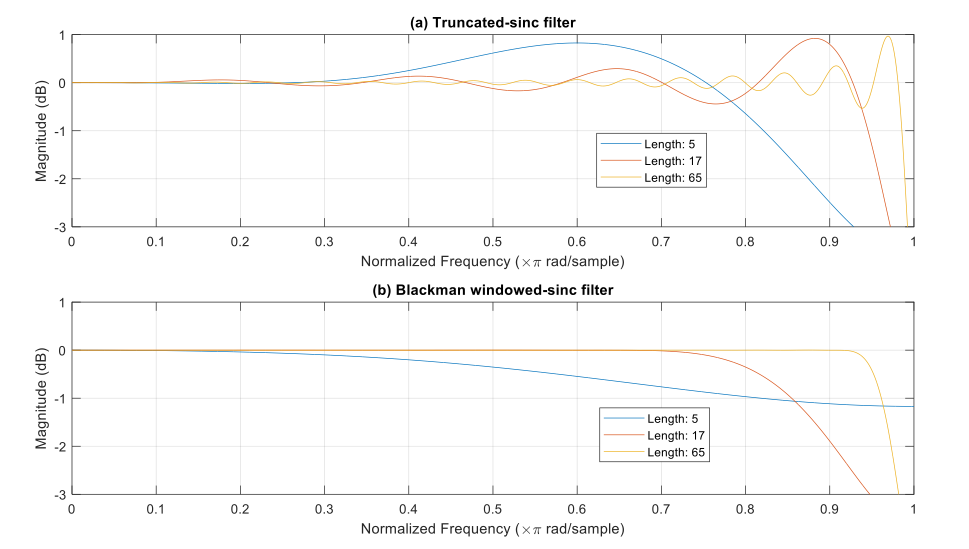
Figure 1: (a) The frequency response of the directly truncated sinc filter exhibits significant ripples. (b) The frequency response of the Blackman windowed-sinc filter shows minimum ripples.
A windowed sinc
To realise an ideal brick-wall frequency response requires an infinitely long sinc function and therefore an infinite number of filter taps. The length of a real FIR filter cannot be infinite, and the sinc filter must be truncated. Truncating the filter is equivalent to multiplying by a rectangular window in the time domain. As noted above, this will result in convolution of our brick-wall response with a sinc function in the frequency domain, degrading the magnitude response of the filter. This error is worse for short filters but only improves slowly with 1/(filter length), as illustrated in Figure 1(a).
The errors associated with truncation can be reduced by windowing the sinc function to avoid sharp discontinuities at the edges. Numerous windows exist offering trade-offs between bandwidth and passband flatness. In Figure 1(b), a Blackman windowing function was applied to achieve a relatively flat frequency response, as is desirable for an all-pass delay filter.
Equation editor
The FIR Filter Builder instrument offers a variety of configurable filters, specified in both time and frequency domains. Moreover, it is possible to upload a custom impulse response or define one using the built-in equation editor. Although the sinc function is included as a pre-defined option, as an educational exercise, we show here how it could be realised using the equation editor.
Mathematically, the sinc filter that achieves band-limited unity gain within the Nyquist frequency range can be expressed as:
![]()
where: m is the desired delay in units of the sampling period Ts= 1/fs
The time length of the sinc filter is Ts (Ntaps-1). However, in the FIR Filter Builder, the Equation editor has a nominal time base of 1. To preserve the sinc filter shape within the FIR Filter Builder, n in Eq. 6 must be reduced by a factor of Ts (Ntaps-1). Therefore, the filter equation for FIR Filter Builder becomes:

One important consideration is that the sinc function in Eq. 7 is defined over the interval ![]() . To position the center of the sinc filter at the center of the FIR filter window and preserve causality (shifting the definition range to [0,Ntaps-1] ), the expression can be further refined to:
. To position the center of the sinc filter at the center of the FIR filter window and preserve causality (shifting the definition range to [0,Ntaps-1] ), the expression can be further refined to:

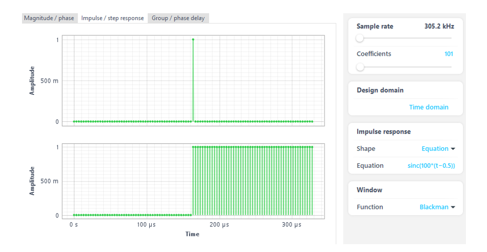
Figure 2: FIR filter Channel A configuration for a delay of 50 sampling periods.
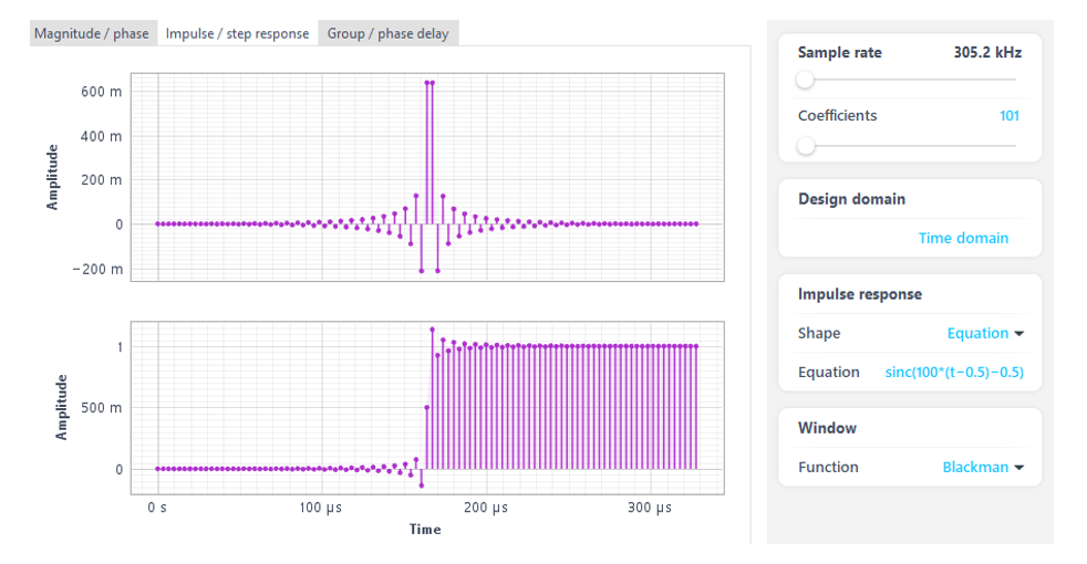
Figure 3: FIR filter ChannelB configuration for a delay of 50.5 sampling periods.
Example
Figure 2 and Figure 3 depict the configurations of two channels in the FIR Filter Builder. In Channel A, a delay of 50 sampling periods is provided, and the filter coefficients exhibit a single peak located precisely in the center. This peak essentially represents a Delta function δ[n-50]. Channel B accurately displays a digitized sinc function. The center of the sinc function is located between two FIR taps, resulting in the absence of a single peak value. This path delays the input signal by 50.5 samples. Figure 4 demonstrates the accurate realization of a 1/2 sampling period delay between the two paths.
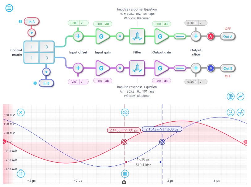
Figure 4: A 1/2 sampling period lag compared to Channel A (red) can be observed on Channel B (blue).
Conclusion
The precise alignment of signals and the compensation of delays are important in various control and signal transmission applications. The utilization of the robust FIR Filter Builder enables highly accurate control over signal line delays. Additionally, FIR Filter Builder can be seamlessly combined with other instruments and custom Moku Cloud Compile code within Multi-Instrument Mode to ensure precise and accurate results even in complicated integrated testing environments.
To learn more about fractional delay generation, read the application note.


