In this series, we provide a practical reference for designing and debugging loops by presenting a short introduction to feedback control as encountered in the frequency domain.
5.1 Introduction
It often occurs that a loop can be closed and the required performance realized only for control to be lost after a short period of time. A common culprit in such situations is actuator saturation. In these cases, the actuator is ‘fast’ enough to mitigate the highest-frequency elements of the disturbance but it does not have the requisite absolute range to cope with its lowest-frequency components.
For instance, when locking a laser to a cavity, the laser’s piezoelectric motor (PZT) is initially able to hold the laser on resonance. However, environmental thermal effects cause the length of the cavity to increase (say) with time. As a result, the ‘DC’ component of the PZT control signal increases monotonically until either the electronics or the PZT itself ‘rail’ and lock is lost. In this part of our series on frequency-domain control we consider how to solve this problem through the addition of a second actuator.
Part 1 establishes the definition of a transfer function and provides the components from which one can construct control loop block diagrams to model elaborate systems. In Part 2 we demonstrate how feedback control systems can be used to suppress disturbances or track a process set point. The complications associated with noisy sensors are also discussed. Unlike open-loop systems, devices under feedback control have the potential to become unstable and there is tension between performance and robustness. Ultimately, delays in signal propagation can impose the most stringent limit. These issues are treated in Part 3. In the frequency domain, most parameters of a feedback system can be linked to its open-loop transfer function. In Part 4 we explain how to measure this important quantity and provide a list of functions often used in shaping it. Here, Part 5 describes one method of avoiding actuator saturation and, in doing so, introduces ideas useful to the treatment of multiple actuators. Our series concludes in Part 6 with the study of the PID controller. This common control architecture is generally considered from a time-domain point-of-view; we illustrate the complementary frequency-domain representation.
5.2 An additional actuator
The obvious option in this scenario is to replace the saturating actuator with one offering a larger range. Generally, this strategy fails, as increasing range results in a commensurate reduction in speed. This knowledge, nevertheless, points to another solution: we can augment the system with a second actuator providing larger range which, although slow, is capable of counteracting the disturbances at the lowest frequencies.
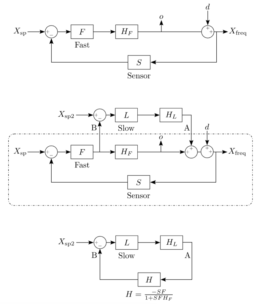
This approach is illustrated in Figure 5.1. The uppermost diagram represents the initial loop where only the fast actuator, with transfer function \(H_F\), is included. The fast controller and system sensor have transfer functions F and S, respectively. This loop is stable with OLTF \(SFH_F\).

Figure 5.1: Top: Initial ‘fast loop’. Middle: Fast loop augmented with slow loop to avoid saturation. Bottom: Equivalent loop considering the fast loop as the plant.
The middle diagram depicts the same system with the addition of the slow actuator (transfer function \(H_L\)) and slow controller (transfer function L). This new path takes as its input the fast actuator’s control signal. Our goal is to reduce this signal to avoid saturation.
5.3 A change in point of view
In order to determine the stability and performance of the new path we have added we must change our point of view. Since the fast loop is itself stable, we consider it as the plant for the new path.
By dint of the techniques outlined above, we compute the transfer function between points A and B and condense the fast system into a single block, as demonstrated in the lowermost diagram of Figure 5.1. Said transfer function is given by
\(H = frac{-SF}{1+SFH_F}\)
and the OLTF of our new ‘slow’ loop is
\(G = frac{LH_L}{H_F}frac{-SFH_F}{1+SFH_F}\).
The slow loop necessarily has a low UGF relative to the initial fast loop. Below the UGF of the fast loop \(-SFH_F/(1+SFH_F) sim -1\). Thus at frequencies of interest for the slow loop,
\(G sim -frac{LH_L}{H_F}\),
this expression can be used to determine the performance and stability of the slow loop as normal, with the caveat that L usually requires negative gain to accommodate the phase of the negative feedback loop H.
5.4 Desaturation
Recall that the initial goal of the slow loop was to reduce the control burden falling on the fast actuator. With this in mind, we examine the output o of the fast actuator in response to a frequency disturbance d (see Figure 5.1).
With the original fast path acting alone we find
\(o = frac{-SFH_F}{1+SFH_F}d sim – d\),
Broadly speaking, inside the fast-loop bandwidth, the fast actuator generates the inverse of the disturbance so that the output remains unperturbed.
With the addition of the slow path we have
\(o = frac{-SFH_F}{1+SFH_F-SFLH_L}d sim – frac{d}{G}\),
where the approximation is valid inside the bandwidth of the slow loop. Therefore, at frequencies where the slow loop is active, the fast path output is reduced by G, the gain of the slow loop. Should this reduced output fall within the useful range of the fast actuator, saturation will be avoided and closed-loop operation will be possible over long timescales.
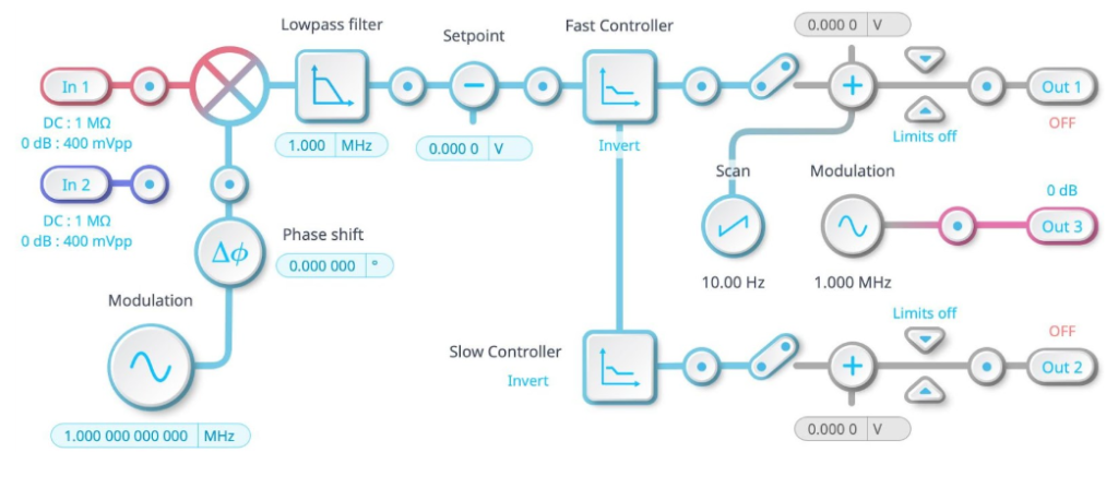
The Moku Laser Lock Box implements fast and slow paths using the architecture described above, allowing users to easily deploy actuator desaturation techniques (see Figure 5.2).

Figure 5.2: The Moku Laser Lock Box includes fast and slow feedback paths. The output of the fast controller is routed to the input of the slow controller. This architecture can avoid saturation of the fast path.
5.5 Summary
Above we have shown how the combination of two actuators, providing useful performance over different frequency bands, can mitigate the problem of actuator saturation. The key idea is that the mathematical treatment we introduced in earlier parts is flexible; we can change our point of view and consider an entire feedback loop as just another block in a simpler control system diagram. This concept can be applied to situations where we seek to increase bandwidth through the addition of a faster actuator or where we have multiple actuators operating in parallel, as opposed to the cascaded architecture we examined. The new, simpler, diagram also allowed us to easily investigate the stability of the compound configuration with our pre-existing tools.
In the next, and last, part of our series, Part 6, we shall focus on the ever-present PID controller.


