This recap and Q+A complement our webinar, entitled Digital PDH locking: A modern approach to laser frequency stabilization, which we co-hosted with Optica on October 17, 2024. If you weren’t able to attend live, you can register now for on-demand access.
In addition to a webinar summary, we’re providing in-depth answers to select audience questions below.
Webinar recap
This webinar consisted of three segments. In the first segment, we discussed the motivations and methods for stabilizing a laser, as well as its applications. We also shared different techniques for locking a laser to an optical reference cavity, including side-of-fringe locking, dither locking, and Pound-Drever-Hall (PDH) laser locking, with the relative advantages and disadvantages of each.
In the second segment, we presented a deep pedagogical dive into the physics of laser locking. We explored signal processing topics such as phase modulation, I/Q signals, and cavity dynamics, alongside graphical aids to help visualize the processes of PDH error signal generation.
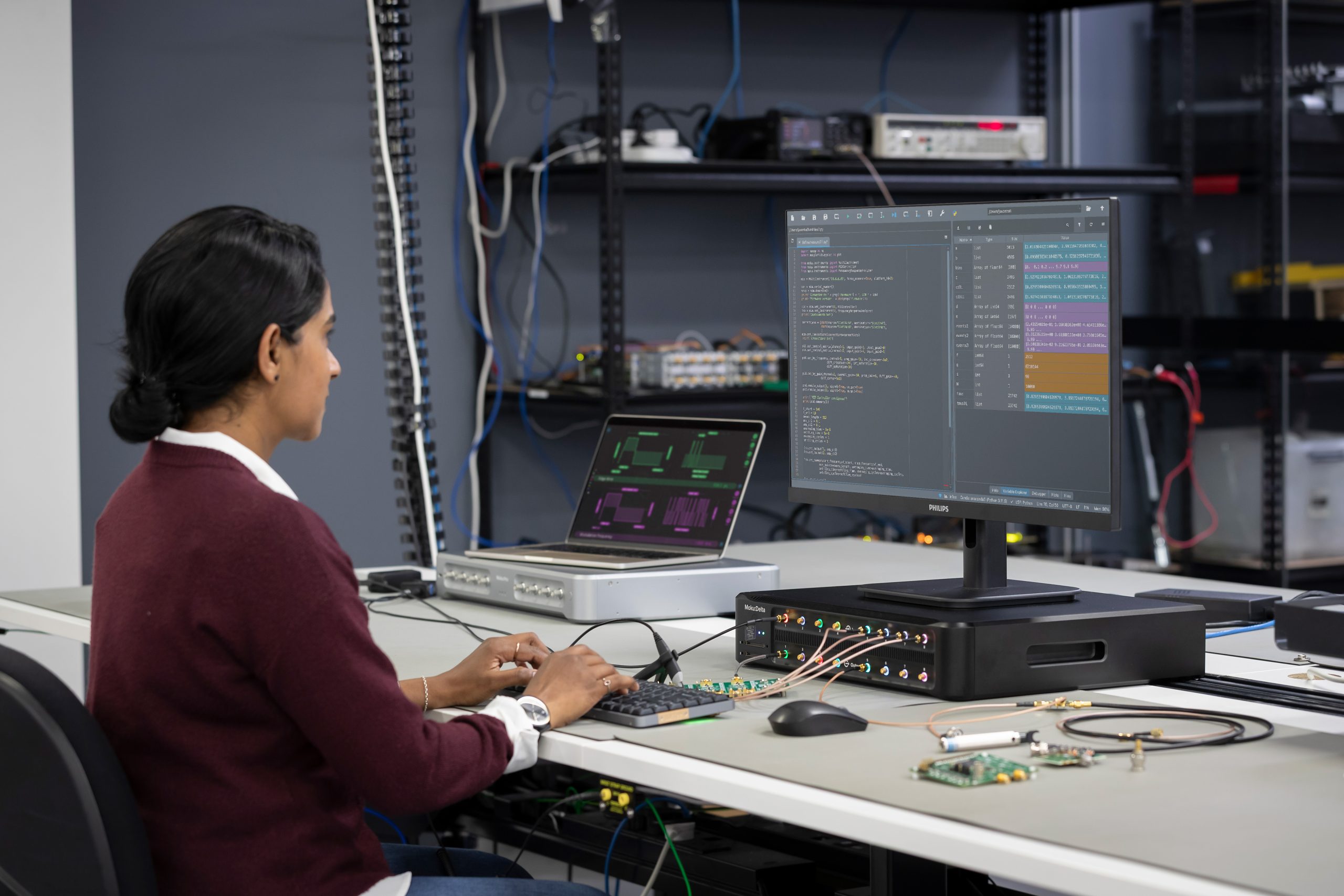
In the final segment, we performed a live demonstration of the FPGA-based Moku Laser Lock Box as an all-in-one laser stabilization tool. We emulated a laser locking setup using Multi-Instrument Mode entirely on Moku:Pro, with a Moku Waveform Generator acting as a frequency source and the Moku Digital Filter Box as the reference cavity. We established a lock to our pseudo-cavity using the PDH method.
Audience questions
Can you use either the transmission or reflection PD for the classic PDH setup? Which is better for PDH locking?
While it is technically possible to use cavity transmission for PDH locking, this does nullify many of the advantages of the technique. One of the main benefits of the PDH technique is that the modulation frequency can be many times larger than the cavity linewidth. This generates two sidebands that are far off-resonant from the cavity and almost entirely reflected by the mirror. These sidebands then mix with the original signal, essentially functioning as references that track the central frequency. In transmission mode, these sidebands do not pass through the cavity and cannot be used for mixing with the carrier frequency.
To use the PDH technique in transmission, the modulation frequency can be reduced to fit the sidebands inside the cavity linewidth. However, this severely limits the response range and speed of the laser locking, and the technique can fail if the laser frequency drifts too far from the expected value. If you have a relatively quiet laser without much jitter, transmission PDH locking can suffice. For most commercial lasers, locking with reflected power is likely the more effective option.
Can you run multiple instruments simultaneously, either through scripting or the interface? What are the limitations when using Moku:Go for laser locking compared to Moku:Pro?
Yes, Moku supports Multi-Instrument Mode, which allows users to partition the FPGA and place up to four (on Moku:Pro) or two (on Moku:Lab and Moku:Go) instruments side-by-side. Multi-Instrument Mode can be activated and configured either through the Moku software interface (see Figure 1), or any of the APIs available for other software platforms (for example, Python). The settings for the different instruments can be configured in parallel with multi-window viewing.
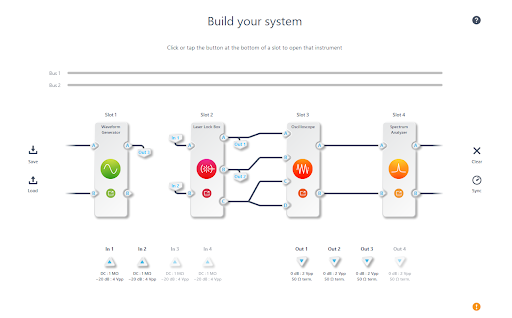
Figure 1: On Moku:Pro, the Laser Lock Box takes one instrument slot.
However, there are some important distinctions to note between Moku hardware models. While the Laser Lock Box can be used on Moku:Lab and Moku:Go, it cannot be used in Multi-Instrument Mode and must be run as a standalone instrument. On Moku:Pro, the Laser Lock Box can be deployed in one of four instrument slots. Moku:Go has a smaller form factor and a lower input bandwidth (30 MHz), which is still sufficient for many locking configurations, as well as monitoring control loops via the PID controller. To learn more, check out our case study featuring research from the University of Bristol. See the product specifications for Moku:Pro and Moku:Go determine which device fits your needs.
Can you evaluate the quality of a laser with Moku, such as an RIN measurement?
RIN stands for relative intensity noise measurement, a technique that evaluates the quality of a laser by plotting the power fluctuation (relative to average output power) as a function of frequency. A Moku Spectrum Analyzer can measure the RIN in a configuration similar to the one in Figure 2. First, the laser under test emits a beam, which is usually heavily attenuated so as to not overwhelm the detector. The photoreceiver emits a voltage proportional to the input laser power. To ensure the signal power exceeds the noise floor of the spectrum analyzer, the photoreceiver current is first passed through a low-noise amplifier. The Spectrum Analyzer performs a power spectral density (PSD) measurement, which measures the distribution of laser power across frequency components. After collection, the signal can be normalized by the average laser power to obtain the RIN data.
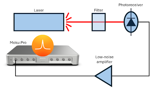
Figure 2: Relative intensity noise measurement using the Moku Spectrum Analyzer.
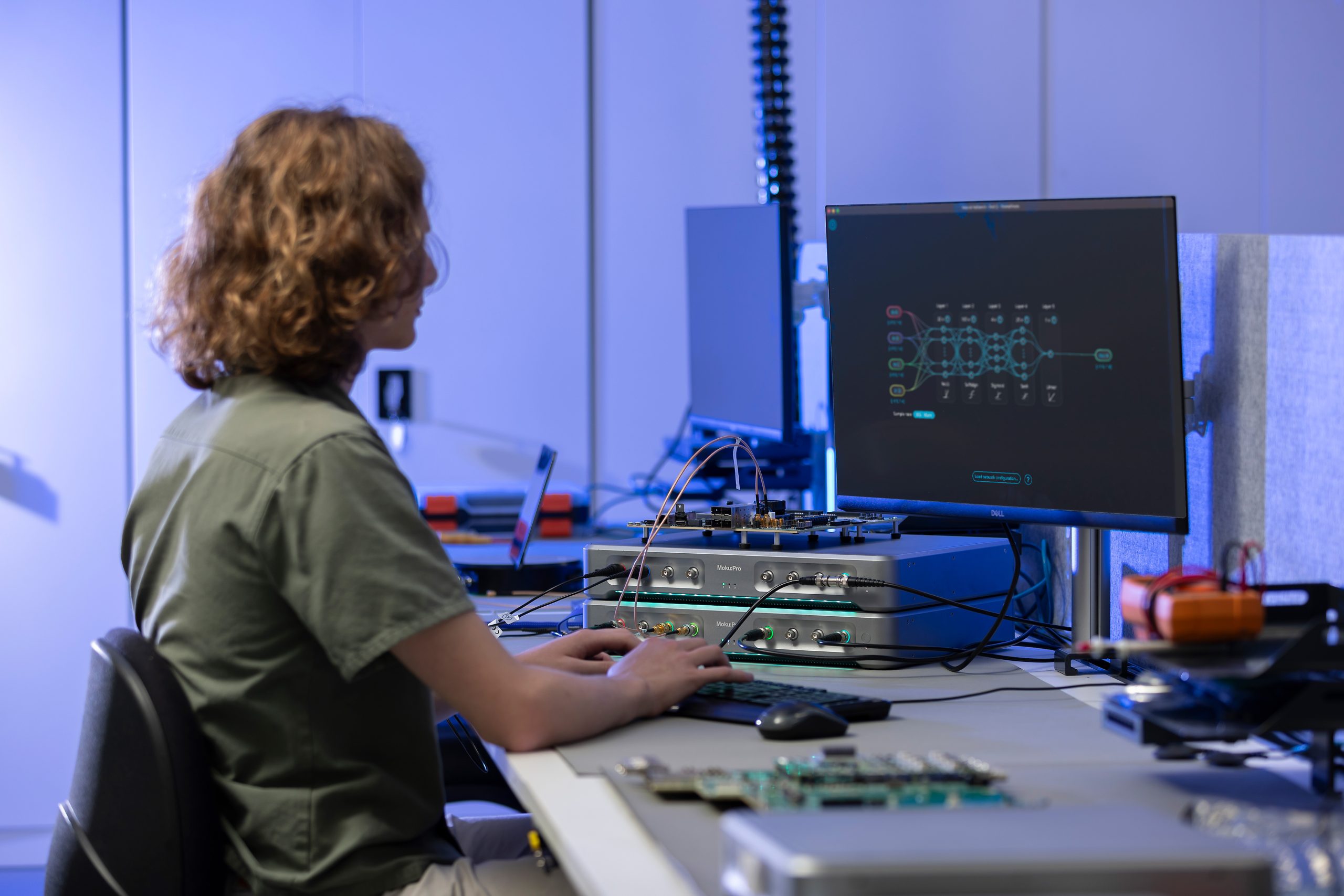
Is there any trick to PID control for better locking?
The PID parameters needed for different experiments can vary immensely, and as such there is not a standard process for optimizing PID parameters. Some algorithmic processes, like the Ziegler-Nichols method, exist to help with automation. Recently, neural networks have attracted interest for their potential to control closed feedback loops.
We are happy to provide some general tips. It is often desirable to set the gain as high as possible at frequencies where there is noise (usually low frequencies) and as low as possible where sensing noise dominates (usually at higher frequencies). The unity gain will then be at intermediate frequencies, which is where the stability of the system must be carefully addressed.
Thank you for viewing our webinar. We look forward to seeing you again.
For more insightful demonstrations, check out our webinar library for on-demand viewing.
More questions?
Get answers to FAQs in our Knowledge Base
If you have a question about a device feature or instrument function, check out our extensive Knowledge Base to find the answers you’re looking for. You can also quickly see popular articles and refine your search by product or topic.
Join our User Forum to stay connected
Want to request a new feature? Have a support tip to share? From use case examples to new feature announcements and more, the User Forum is your one-stop shop for product updates, as well as connection to Liquid Instruments and our global user community.