Oscilloscopes are test instruments that capture time-varying electronic signals, allowing the user to analyze features of these signals such as period, frequency, phase, and amplitude. Informally known as “scopes,” they are ubiquitous in physics and engineering labs worldwide and used by hobbyists, students, and professionals alike for debugging, characterization, and data collection. An oscilloscope can often record multiple signals, or traces, simultaneously and can be swept continuously or programmed to collect traces only after a specific trigger event. Portable and versatile, scopes are a cornerstone of electronic testing at any level. A USB oscilloscope takes these desirable traits of a traditional oscilloscope and improves upon them without sacrificing performance.
What makes a USB oscilloscope different from a traditional oscilloscope?
The traditional oscilloscope described above most often features its own built-in screen and user interface (UI), increasing both the cost and physical footprint of the device. Moreover, the user must manually retrieve data from the oscilloscope via a LAN connection or thumb drive. A USB oscilloscope, on the other hand, is a more compact version of this device that connects to a computer via a USB port. The computer acts as the oscilloscope’s display and UI, allowing the manufacturer to forgo these extra costs and focus on improving the software and user experience.
What are the advantages of a USB oscilloscope?
Portability: Given the fact that a USB oscilloscope does not have a physical display or UI, it is much more portable than its benchtop counterparts. This makes them ideal for fieldwork or laboratory environments with limited space.
Cost-effectiveness: Due to the reduced complexity, a USB oscilloscope is often less expensive than a traditional oscilloscope. The reduction in cost makes them accessible to users who are on a budget.
Versatility: Since it acts as the oscilloscope’s UI and display, the accompanying software often includes more features such as data logging and the ability to easily share and store data.
Ease of use: The UI for a USB oscilloscope can be more intuitive for users more familiar with computers than traditional lab equipment, such as undergrad students and junior researchers.
What are some applications for a USB oscilloscope?
An oscilloscope is an incredibly versatile instrument that can be used across a broad range of fields. The list below features some of these applications, although it is not exhaustive.
Electronics and power systems design: Engineers use oscilloscopes to assist in the design, testing, and debugging of electronic circuits. The ability to view and measure AC and DC voltages as a function of time helps ensure that components function as intended, both in the small- and large-scale. In larger-scale commercial productions, oscilloscopes also help verify that electronic components and systems meet rigorous quality and performance standards. Lastly, oscilloscopes can be used to measure and analyze the performance of electrical power systems, including inverters, converters, and power supply units.
Automotive diagnostics: Technicians and researchers in the automotive industry use oscilloscopes to debug and diagnose problems with many automobile components such as sensors, actuators, and switches. Oscilloscopes can also test communication data streams for vehicles.
Education and training: Oscilloscopes are ubiquitous in educational institutions for their easy-to-use nature and their usefulness in demonstrating undergraduate-level electronics principles common to physics and engineering curricula. They can also assist students in performing basic electronic laboratory experiments and circuit building.
Telecommunications: Engineers use oscilloscopes to analyze and troubleshoot issues with communications systems. Technicians can diagnose signal integrity issues, view the bandwidth of a given signal in real time, and calculate data transmission rates.
Research and development: Researchers in many scientific fields use oscilloscopes, including but not limited to physics, engineering, biomedical, and materials science. Oscilloscopes in research labs are used in a wide range of experiments for data collection and analysis.
Audio and acoustics: Oscilloscopes are not limited to the electromagnetic realm and can help in analyzing digitized audio signals, designing sound equipment, and troubleshooting issues in audio systems.
What are the key technical specifications of a USB oscilloscope?
Channel count: The number of traces that can be measured simultaneously. Both a traditional and USB oscilloscope typically offer two to four channels. The ability to do math operations on the data is usually not counted as a separate channel.
Bandwidth: The range of frequencies the oscilloscope can accurately measure. Outside of the specified bandwidth, the measured power of the signal will start to roll off quickly. Higher bandwidths are necessary for observing faster signals. Low- to medium-cost oscilloscopes may have ranges in the tens to hundreds of megahertz, whereas high-end models may surpass 1 GHz.
Sampling rate: The speed at which the oscilloscope samples the signal. This is related to the bandwidth as the sampling rate must, at minimum, be twice the stated bandwidth of the oscilloscope (see the Nyquist theorem). However, the sampling rate is often much higher than the Nyquist frequency in order to improve the fidelity of the acquired signal. A high sampling rate can reduce aliasing and provide more time resolution for signal plotting and processing.
Resolution: The smallest voltage change that can be measured. This number is determined by both the input voltage range and the number of bits. Most oscilloscopes are typically 8 or 12 bits, and have voltage ranges that can be adjusted from ± 50 mV to ± 50 V or more. The higher resolution offers a more detailed analysis of signals, but more bit resolution often comes at the cost of sampling speed.
Maximize flexibility and performance with an FPGA-based, digital USB oscilloscope
The Moku Oscilloscope is one of 13 software-defined instruments available on all models of the FPGA-based Moku family. When used as a single instrument, with the interface and settings viewable via the Moku: app, the Oscilloscope offers four channels for signal collection and a math channel that can perform a variety of operations on the trace data, including addition, multiplication, Fourier analysis, and X-Y plotting. The user can also make measurements of relative phase, frequency, and duty cycle between any of the four channels in real time. The Oscilloscope also supports both internal and external triggering and contains an embedded Moku Waveform Generator. Figure 1 shows the scope being used in single-instrument mode, with the settings of each channel viewable on the right-hand side. Traces and settings from the Oscilloscope can easily be exported in .csv format with the Moku: app, which can connect a PC or Mac to the Moku device via LAN, USB-C, or Wi-Fi.
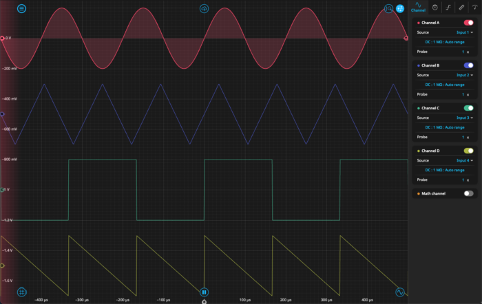
Figure 1: Using the digital oscilloscope in single instrument mode. The Moku Oscilloscope can plot up to four inputs simultaneously, as well as a math channel.
In addition, the Moku Oscilloscope can also function with two input channels in Multi-instrument Mode. Multi-instrument Mode partitions the FPGA of the Moku device so that multiple instruments can function simultaneously. This allows the scope to easily integrate with other Moku instruments such as the Logic Analyzer, Waveform Generator, or Phasemeter. Running the Oscilloscope in this way, with all-digital connections between instruments, eliminates the insertion loss and phase drift that is characteristic of analog setups.
For an example use, Figure 2 shows Moku:Pro configured in Multi-instrument mode as a phase-locked loop. In this setup, the Moku Phasemeter in Slot 2 measures a simple sine wave produced by the Waveform Generator and generates a phase-locked output. The Oscilloscope is used to monitor the output of both the Waveform Generator and Phasemeter and to verify that the phase-locking is working.
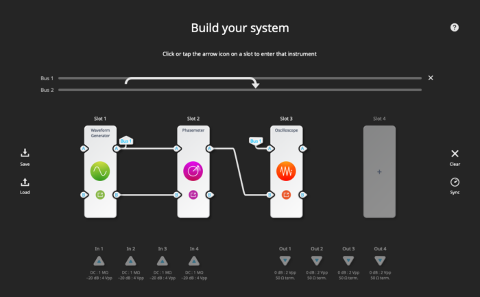
Figure 2: Using the digital oscilloscope in Multi-instrument mode. The oscilloscope in Channel 3 measures the output from the Waveform Generator and Phasemeter simultaneously.
Choosing the right USB oscilloscope
A digital USB oscilloscope such as the Moku Oscilloscope offers a convenient and cost-effective solution for signal analysis. The multiple instruments available on the device, digital connections between instruments, and small form factor make the Moku especially useful in situations where physical space and budget are limited. While retaining all the functionality of a traditional standalone oscilloscope, it also delivers significant advantages in terms of versatility and ease of use.
To learn more about the Moku Oscilloscope, check out these resources:
Case study: Building a sustainable, competitive solar car with Moku:Go and the Chalmers Solar Team
Case study: Auto-aligning optical cavity systems with Moku:Go
Webinar: Achieving precise phase control in optical applications with digital phase-locked loops
Questions?
Get answers to FAQs in our Knowledge Base
If you have a question about a device feature or instrument function, check out our extensive Knowledge Base to find the answers you’re looking for. You can also quickly see popular articles and refine your search by product or topic.
Join our User Forum to stay connected
Want to request a new feature? Have a support tip to share? From use case examples to new feature announcements and more, the User Forum is your one-stop shop for product updates, as well as connection to Liquid Instruments and our global user community.


