




Please update your browser. For the best Liquid Instruments experience, update to the latest version of Chrome, Edge, Firefox, or Safari. Update Microsoft Edge.
Liquid Instruments Logo
Products
Hardware Platforms
Moku:Delta
Moku:Delta
New
For advanced design and validation
Moku:Pro
Moku:ProFor versatile test and measurement
Moku:Lab
Moku:LabFor experimental research labs
Moku:Go
Moku:GoFor quick testing and debugging
Compare Hardware
Compare HardwareView a side-by-side of all Moku hardware
Technologies
GenInst Studio
New
Generate personalized instruments
Integrated InstrumentsProfessional-grade instruments at your fingertips
Neural NetworkFPGA-powered neural network integration
Multi-Instrument ModeCombine instruments to create a customized test system
Moku CompileCode, compile, and deploy to your Moku's FPGA
Software
MokuOSDownload the Moku app for Windows, macOS, iPadOS & visionOS
APIsPython, MATLAB, LabVIEW
UtilitiesCommand line and graphical tools for file conversion
Instruments
Analysis
Oscilloscope
Spectrum Analyzer
Frequency Response Analyzer
Lock-in Amplifier
Phasemeter
Logic Analyzer / Pattern Generator
Time & Frequency Analyzer
Data Logger
Generation
Waveform Generator
Arbitrary Waveform Generator
Control & Conditioning
PID Controller
Digital Filter Box
FIR Filter Builder
Laser Lock Box
Custom & Utility
GenInst Studio
New
Gigabit Streamer
Custom Instrument
Neural Network
Multi-Instrument Mode
Applications
Optics and Photonics
Microscopy and Spectroscopy
Photon Counting
Quantum Optics
Aerospace and defense
A&D Instrumentation
Component Test
Automated Testing
Semiconductor Test
Control Systems and Bode Analysis
MEMS Testing
AI and Machine Learning
Generative Instrumentation
New
Neural Networks
Education
Education and Research
Resources
App Notes
Blog
Case Studies
Coursework
Guides
Product Documentation
Publications
Webinars
White Papers
Support
Company
Contact Us
About Us
Leadership
Partners
News & Updates
Press
Events Calendar
Careers
Store
Moku:Delta
Moku:Pro
Moku:Go
Upgrade Moku:Pro
Upgrade Moku:Lab
Upgrade Moku:Go
0
Get a quote Buy Now
Blog

Understanding 1/f noise (flicker noise)

1/f, or flicker noise, is a key characteristic of semiconductor devices. Learn how to measure and mitigate this phenomenon.

Jessica PattersonProduct Marketing Manager • September 5, 2025

    [4] “Fundamentals of Precision ADC Noise Analysis.” Accessed: Sep. 04, 2025. [Online]. Available: https://www.ti.com/lit/eb/slyy192a/slyy192a.pdf?ts=1757009681439

    [5] R. F. Voss, “1/f (Flicker) Noise: A Brief Review,” 33rd Annual Symposium on Frequency Control, Atlantic City, NJ, USA, 1979, pp. 40-46, doi: 10.1109/FREQ.1979.200297.

    [/vc_column_text][/vc_column][/vc_row]

    ‌[2] “Understanding and Eliminating 1/f Noise | Analog Devices,” Analog.com, 2024. https://www.analog.com/en/resources/analog-dialogue/articles/understanding-and-eliminating-1-f-noise.html

    [3] “MT-048 TUTORIAL Op Amp Noise Relationships: 1/f Noise, RMS Noise, and Equivalent Noise Bandwidth.” Available: https://www.analog.com/media/en/training-seminars/tutorials/MT-048.pdf

    [4] “Fundamentals of Precision ADC Noise Analysis.” Accessed: Sep. 04, 2025. [Online]. Available: https://www.ti.com/lit/eb/slyy192a/slyy192a.pdf?ts=1757009681439

    [5] R. F. Voss, “1/f (Flicker) Noise: A Brief Review,” 33rd Annual Symposium on Frequency Control, Atlantic City, NJ, USA, 1979, pp. 40-46, doi: 10.1109/FREQ.1979.200297.

    [/vc_column_text][/vc_column][/vc_row]

    [1] “Pink noise,” Wikipedia, Nov. 07, 2020. https://en.wikipedia.org/wiki/Pink_noise

    ‌[2] “Understanding and Eliminating 1/f Noise | Analog Devices,” Analog.com, 2024. https://www.analog.com/en/resources/analog-dialogue/articles/understanding-and-eliminating-1-f-noise.html

    [3] “MT-048 TUTORIAL Op Amp Noise Relationships: 1/f Noise, RMS Noise, and Equivalent Noise Bandwidth.” Available: https://www.analog.com/media/en/training-seminars/tutorials/MT-048.pdf

    [4] “Fundamentals of Precision ADC Noise Analysis.” Accessed: Sep. 04, 2025. [Online]. Available: https://www.ti.com/lit/eb/slyy192a/slyy192a.pdf?ts=1757009681439

    [5] R. F. Voss, “1/f (Flicker) Noise: A Brief Review,” 33rd Annual Symposium on Frequency Control, Atlantic City, NJ, USA, 1979, pp. 40-46, doi: 10.1109/FREQ.1979.200297.

    [/vc_column_text][/vc_column][/vc_row]

    Learn more about Moku:Delta here.

    FAQ

    Q: Is 1/f noise the same as flicker noise?

    A: Yes, both terms describe the same thing: low-frequency noise with a spectrum that decreases as frequency increases.

    Q: How is 1/f noise different from white noise?

    A: White noise has constant power across frequencies, while 1/f noise grows stronger at lower frequencies at about 3 dB/decade.

    Q: Where does flicker noise occur?

    A: In semiconductors, resistors, sensors, and even in natural systems outside of electronics.

    Q: How do you measure 1/f noise?

    A: Spectrum analyzers and lock-in amplifiers are common tools. Modern platforms like Moku:Delta combine these in one device, making measurement more efficient.

    References

    [1] “Pink noise,” Wikipedia, Nov. 07, 2020. https://en.wikipedia.org/wiki/Pink_noise

    ‌[2] “Understanding and Eliminating 1/f Noise | Analog Devices,” Analog.com, 2024. https://www.analog.com/en/resources/analog-dialogue/articles/understanding-and-eliminating-1-f-noise.html

    [3] “MT-048 TUTORIAL Op Amp Noise Relationships: 1/f Noise, RMS Noise, and Equivalent Noise Bandwidth.” Available: https://www.analog.com/media/en/training-seminars/tutorials/MT-048.pdf

    [4] “Fundamentals of Precision ADC Noise Analysis.” Accessed: Sep. 04, 2025. [Online]. Available: https://www.ti.com/lit/eb/slyy192a/slyy192a.pdf?ts=1757009681439

    [5] R. F. Voss, “1/f (Flicker) Noise: A Brief Review,” 33rd Annual Symposium on Frequency Control, Atlantic City, NJ, USA, 1979, pp. 40-46, doi: 10.1109/FREQ.1979.200297.

    [/vc_column_text][/vc_column][/vc_row]

    Another key strategy to accurately measure 1/f noise is a low resolution bandwidth and low minimum frequency in your spectrum analyzer. The Moku:Delta and Moku:Pro Spectrum Analyzers can observe signals down to 0 Hz, which is important for low-frequency noise characterization. These spectrum analyzers also allow the user to set a resolution bandwidth as low as 1 Hz, allowing you to accurately capture the 1/f noise without the effects of broadband noise obscuring results. A wider resolution bandwidth integrates more noise power, while a lower resolution bandwidth collects less noise power per resolution bin, leading to a lower displayed noise floor. By reducing the resolution bandwidth to 1 Hz, it is much easier to separate true 1/f characteristics from other noise sources. While 1/f noise is intrinsic to the device under test and measurement system, optimizing your measurement setup to accurately measure flicker noise can build a deeper understanding of the true performance of your device under test.

    Learn more about Moku:Delta here.

    FAQ

    Q: Is 1/f noise the same as flicker noise?

    A: Yes, both terms describe the same thing: low-frequency noise with a spectrum that decreases as frequency increases.

    Q: How is 1/f noise different from white noise?

    A: White noise has constant power across frequencies, while 1/f noise grows stronger at lower frequencies at about 3 dB/decade.

    Q: Where does flicker noise occur?

    A: In semiconductors, resistors, sensors, and even in natural systems outside of electronics.

    Q: How do you measure 1/f noise?

    A: Spectrum analyzers and lock-in amplifiers are common tools. Modern platforms like Moku:Delta combine these in one device, making measurement more efficient.

    References

    [1] “Pink noise,” Wikipedia, Nov. 07, 2020. https://en.wikipedia.org/wiki/Pink_noise

    ‌[2] “Understanding and Eliminating 1/f Noise | Analog Devices,” Analog.com, 2024. https://www.analog.com/en/resources/analog-dialogue/articles/understanding-and-eliminating-1-f-noise.html

    [3] “MT-048 TUTORIAL Op Amp Noise Relationships: 1/f Noise, RMS Noise, and Equivalent Noise Bandwidth.” Available: https://www.analog.com/media/en/training-seminars/tutorials/MT-048.pdf

    [4] “Fundamentals of Precision ADC Noise Analysis.” Accessed: Sep. 04, 2025. [Online]. Available: https://www.ti.com/lit/eb/slyy192a/slyy192a.pdf?ts=1757009681439

    [5] R. F. Voss, “1/f (Flicker) Noise: A Brief Review,” 33rd Annual Symposium on Frequency Control, Atlantic City, NJ, USA, 1979, pp. 40-46, doi: 10.1109/FREQ.1979.200297.

    [/vc_column_text][/vc_column][/vc_row]

    Researchers studying precision electronics, RF systems, or fundamental physics can use Moku:Delta to characterize 1/f noise efficiently and reliably due to this dual ADC sampling. Embedded within Moku:Delta are 15 instruments that can be deployed standalone or as a system, allowing you to use the Spectrum Analyzer, Lock-in Amplifier, Oscilloscope, or Data Logger to measure and record results from your measurements.

    Another key strategy to accurately measure 1/f noise is a low resolution bandwidth and low minimum frequency in your spectrum analyzer. The Moku:Delta and Moku:Pro Spectrum Analyzers can observe signals down to 0 Hz, which is important for low-frequency noise characterization. These spectrum analyzers also allow the user to set a resolution bandwidth as low as 1 Hz, allowing you to accurately capture the 1/f noise without the effects of broadband noise obscuring results. A wider resolution bandwidth integrates more noise power, while a lower resolution bandwidth collects less noise power per resolution bin, leading to a lower displayed noise floor. By reducing the resolution bandwidth to 1 Hz, it is much easier to separate true 1/f characteristics from other noise sources. While 1/f noise is intrinsic to the device under test and measurement system, optimizing your measurement setup to accurately measure flicker noise can build a deeper understanding of the true performance of your device under test.

    Learn more about Moku:Delta here.

    FAQ

    Q: Is 1/f noise the same as flicker noise?

    A: Yes, both terms describe the same thing: low-frequency noise with a spectrum that decreases as frequency increases.

    Q: How is 1/f noise different from white noise?

    A: White noise has constant power across frequencies, while 1/f noise grows stronger at lower frequencies at about 3 dB/decade.

    Q: Where does flicker noise occur?

    A: In semiconductors, resistors, sensors, and even in natural systems outside of electronics.

    Q: How do you measure 1/f noise?

    A: Spectrum analyzers and lock-in amplifiers are common tools. Modern platforms like Moku:Delta combine these in one device, making measurement more efficient.

    References

    [1] “Pink noise,” Wikipedia, Nov. 07, 2020. https://en.wikipedia.org/wiki/Pink_noise

    ‌[2] “Understanding and Eliminating 1/f Noise | Analog Devices,” Analog.com, 2024. https://www.analog.com/en/resources/analog-dialogue/articles/understanding-and-eliminating-1-f-noise.html

    [3] “MT-048 TUTORIAL Op Amp Noise Relationships: 1/f Noise, RMS Noise, and Equivalent Noise Bandwidth.” Available: https://www.analog.com/media/en/training-seminars/tutorials/MT-048.pdf

    [4] “Fundamentals of Precision ADC Noise Analysis.” Accessed: Sep. 04, 2025. [Online]. Available: https://www.ti.com/lit/eb/slyy192a/slyy192a.pdf?ts=1757009681439

    [5] R. F. Voss, “1/f (Flicker) Noise: A Brief Review,” 33rd Annual Symposium on Frequency Control, Atlantic City, NJ, USA, 1979, pp. 40-46, doi: 10.1109/FREQ.1979.200297.

    [/vc_column_text][/vc_column][/vc_row]

    To reduce the effect of 1/f noise at low frequencies, Moku:Pro and Moku:Delta each carry two sets of ADCs on every input channel. One ADC is optimized for low-speed, low-noise measurements. The other is selected for high speed and high performance, ensuring the user does not need to sacrifice bandwidth or accuracy at low frequencies. Signals from both ADCs are acquired simultaneously and blended to construct an optimal measurement signal.

    Researchers studying precision electronics, RF systems, or fundamental physics can use Moku:Delta to characterize 1/f noise efficiently and reliably due to this dual ADC sampling. Embedded within Moku:Delta are 15 instruments that can be deployed standalone or as a system, allowing you to use the Spectrum Analyzer, Lock-in Amplifier, Oscilloscope, or Data Logger to measure and record results from your measurements.

    Another key strategy to accurately measure 1/f noise is a low resolution bandwidth and low minimum frequency in your spectrum analyzer. The Moku:Delta and Moku:Pro Spectrum Analyzers can observe signals down to 0 Hz, which is important for low-frequency noise characterization. These spectrum analyzers also allow the user to set a resolution bandwidth as low as 1 Hz, allowing you to accurately capture the 1/f noise without the effects of broadband noise obscuring results. A wider resolution bandwidth integrates more noise power, while a lower resolution bandwidth collects less noise power per resolution bin, leading to a lower displayed noise floor. By reducing the resolution bandwidth to 1 Hz, it is much easier to separate true 1/f characteristics from other noise sources. While 1/f noise is intrinsic to the device under test and measurement system, optimizing your measurement setup to accurately measure flicker noise can build a deeper understanding of the true performance of your device under test.

    Learn more about Moku:Delta here.

    FAQ

    Q: Is 1/f noise the same as flicker noise?

    A: Yes, both terms describe the same thing: low-frequency noise with a spectrum that decreases as frequency increases.

    Q: How is 1/f noise different from white noise?

    A: White noise has constant power across frequencies, while 1/f noise grows stronger at lower frequencies at about 3 dB/decade.

    Q: Where does flicker noise occur?

    A: In semiconductors, resistors, sensors, and even in natural systems outside of electronics.

    Q: How do you measure 1/f noise?

    A: Spectrum analyzers and lock-in amplifiers are common tools. Modern platforms like Moku:Delta combine these in one device, making measurement more efficient.

    References

    [1] “Pink noise,” Wikipedia, Nov. 07, 2020. https://en.wikipedia.org/wiki/Pink_noise

    ‌[2] “Understanding and Eliminating 1/f Noise | Analog Devices,” Analog.com, 2024. https://www.analog.com/en/resources/analog-dialogue/articles/understanding-and-eliminating-1-f-noise.html

    [3] “MT-048 TUTORIAL Op Amp Noise Relationships: 1/f Noise, RMS Noise, and Equivalent Noise Bandwidth.” Available: https://www.analog.com/media/en/training-seminars/tutorials/MT-048.pdf

    [4] “Fundamentals of Precision ADC Noise Analysis.” Accessed: Sep. 04, 2025. [Online]. Available: https://www.ti.com/lit/eb/slyy192a/slyy192a.pdf?ts=1757009681439

    [5] R. F. Voss, “1/f (Flicker) Noise: A Brief Review,” 33rd Annual Symposium on Frequency Control, Atlantic City, NJ, USA, 1979, pp. 40-46, doi: 10.1109/FREQ.1979.200297.

    [/vc_column_text][/vc_column][/vc_row]

    Lock-in amplifiers are designed to extract weak signals from noisy environments, but flicker noise can complicate these measurements at low frequencies under a few hundred MHz. Since lock-ins operate at reference frequencies, 1/f noise near that frequency can directly degrade sensitivity.

    How to mitigate 1/f noise in test instruments

    To reduce the effect of 1/f noise at low frequencies, Moku:Pro and Moku:Delta each carry two sets of ADCs on every input channel. One ADC is optimized for low-speed, low-noise measurements. The other is selected for high speed and high performance, ensuring the user does not need to sacrifice bandwidth or accuracy at low frequencies. Signals from both ADCs are acquired simultaneously and blended to construct an optimal measurement signal.

    Researchers studying precision electronics, RF systems, or fundamental physics can use Moku:Delta to characterize 1/f noise efficiently and reliably due to this dual ADC sampling. Embedded within Moku:Delta are 15 instruments that can be deployed standalone or as a system, allowing you to use the Spectrum Analyzer, Lock-in Amplifier, Oscilloscope, or Data Logger to measure and record results from your measurements.

    Another key strategy to accurately measure 1/f noise is a low resolution bandwidth and low minimum frequency in your spectrum analyzer. The Moku:Delta and Moku:Pro Spectrum Analyzers can observe signals down to 0 Hz, which is important for low-frequency noise characterization. These spectrum analyzers also allow the user to set a resolution bandwidth as low as 1 Hz, allowing you to accurately capture the 1/f noise without the effects of broadband noise obscuring results. A wider resolution bandwidth integrates more noise power, while a lower resolution bandwidth collects less noise power per resolution bin, leading to a lower displayed noise floor. By reducing the resolution bandwidth to 1 Hz, it is much easier to separate true 1/f characteristics from other noise sources. While 1/f noise is intrinsic to the device under test and measurement system, optimizing your measurement setup to accurately measure flicker noise can build a deeper understanding of the true performance of your device under test.

    Learn more about Moku:Delta here.

    FAQ

    Q: Is 1/f noise the same as flicker noise?

    A: Yes, both terms describe the same thing: low-frequency noise with a spectrum that decreases as frequency increases.

    Q: How is 1/f noise different from white noise?

    A: White noise has constant power across frequencies, while 1/f noise grows stronger at lower frequencies at about 3 dB/decade.

    Q: Where does flicker noise occur?

    A: In semiconductors, resistors, sensors, and even in natural systems outside of electronics.

    Q: How do you measure 1/f noise?

    A: Spectrum analyzers and lock-in amplifiers are common tools. Modern platforms like Moku:Delta combine these in one device, making measurement more efficient.

    References

    [1] “Pink noise,” Wikipedia, Nov. 07, 2020. https://en.wikipedia.org/wiki/Pink_noise

    ‌[2] “Understanding and Eliminating 1/f Noise | Analog Devices,” Analog.com, 2024. https://www.analog.com/en/resources/analog-dialogue/articles/understanding-and-eliminating-1-f-noise.html

    [3] “MT-048 TUTORIAL Op Amp Noise Relationships: 1/f Noise, RMS Noise, and Equivalent Noise Bandwidth.” Available: https://www.analog.com/media/en/training-seminars/tutorials/MT-048.pdf

    [4] “Fundamentals of Precision ADC Noise Analysis.” Accessed: Sep. 04, 2025. [Online]. Available: https://www.ti.com/lit/eb/slyy192a/slyy192a.pdf?ts=1757009681439

    [5] R. F. Voss, “1/f (Flicker) Noise: A Brief Review,” 33rd Annual Symposium on Frequency Control, Atlantic City, NJ, USA, 1979, pp. 40-46, doi: 10.1109/FREQ.1979.200297.

    [/vc_column_text][/vc_column][/vc_row]

    Spectrum analyzers are commonly used to observe noise across frequencies. However, at very low frequencies, their own internal noise can dominate, making it hard to distinguish between the instrument noise floor and the actual 1/f noise of the device under test. Finding a low-noise spectrum analyzer at low frequencies can be difficult and expensive.

    1/f noise in lock-in amplifiers

    Lock-in amplifiers are designed to extract weak signals from noisy environments, but flicker noise can complicate these measurements at low frequencies under a few hundred MHz. Since lock-ins operate at reference frequencies, 1/f noise near that frequency can directly degrade sensitivity.

    How to mitigate 1/f noise in test instruments

    To reduce the effect of 1/f noise at low frequencies, Moku:Pro and Moku:Delta each carry two sets of ADCs on every input channel. One ADC is optimized for low-speed, low-noise measurements. The other is selected for high speed and high performance, ensuring the user does not need to sacrifice bandwidth or accuracy at low frequencies. Signals from both ADCs are acquired simultaneously and blended to construct an optimal measurement signal.

    Researchers studying precision electronics, RF systems, or fundamental physics can use Moku:Delta to characterize 1/f noise efficiently and reliably due to this dual ADC sampling. Embedded within Moku:Delta are 15 instruments that can be deployed standalone or as a system, allowing you to use the Spectrum Analyzer, Lock-in Amplifier, Oscilloscope, or Data Logger to measure and record results from your measurements.

    Another key strategy to accurately measure 1/f noise is a low resolution bandwidth and low minimum frequency in your spectrum analyzer. The Moku:Delta and Moku:Pro Spectrum Analyzers can observe signals down to 0 Hz, which is important for low-frequency noise characterization. These spectrum analyzers also allow the user to set a resolution bandwidth as low as 1 Hz, allowing you to accurately capture the 1/f noise without the effects of broadband noise obscuring results. A wider resolution bandwidth integrates more noise power, while a lower resolution bandwidth collects less noise power per resolution bin, leading to a lower displayed noise floor. By reducing the resolution bandwidth to 1 Hz, it is much easier to separate true 1/f characteristics from other noise sources. While 1/f noise is intrinsic to the device under test and measurement system, optimizing your measurement setup to accurately measure flicker noise can build a deeper understanding of the true performance of your device under test.

    Learn more about Moku:Delta here.

    FAQ

    Q: Is 1/f noise the same as flicker noise?

    A: Yes, both terms describe the same thing: low-frequency noise with a spectrum that decreases as frequency increases.

    Q: How is 1/f noise different from white noise?

    A: White noise has constant power across frequencies, while 1/f noise grows stronger at lower frequencies at about 3 dB/decade.

    Q: Where does flicker noise occur?

    A: In semiconductors, resistors, sensors, and even in natural systems outside of electronics.

    Q: How do you measure 1/f noise?

    A: Spectrum analyzers and lock-in amplifiers are common tools. Modern platforms like Moku:Delta combine these in one device, making measurement more efficient.

    References

    [1] “Pink noise,” Wikipedia, Nov. 07, 2020. https://en.wikipedia.org/wiki/Pink_noise

    ‌[2] “Understanding and Eliminating 1/f Noise | Analog Devices,” Analog.com, 2024. https://www.analog.com/en/resources/analog-dialogue/articles/understanding-and-eliminating-1-f-noise.html

    [3] “MT-048 TUTORIAL Op Amp Noise Relationships: 1/f Noise, RMS Noise, and Equivalent Noise Bandwidth.” Available: https://www.analog.com/media/en/training-seminars/tutorials/MT-048.pdf

    [4] “Fundamentals of Precision ADC Noise Analysis.” Accessed: Sep. 04, 2025. [Online]. Available: https://www.ti.com/lit/eb/slyy192a/slyy192a.pdf?ts=1757009681439

    [5] R. F. Voss, “1/f (Flicker) Noise: A Brief Review,” 33rd Annual Symposium on Frequency Control, Atlantic City, NJ, USA, 1979, pp. 40-46, doi: 10.1109/FREQ.1979.200297.

    [/vc_column_text][/vc_column][/vc_row]

    When signals are digitized and analyzed, flicker noise can distort results, obscure weak signals, and complicate filtering requirements. Understanding the noise floor of your measurement system and knowing how much of it is due to 1/f contributions is crucial for accurate results.

    1/f noise in spectrum analyzers

    Spectrum analyzers are commonly used to observe noise across frequencies. However, at very low frequencies, their own internal noise can dominate, making it hard to distinguish between the instrument noise floor and the actual 1/f noise of the device under test. Finding a low-noise spectrum analyzer at low frequencies can be difficult and expensive.

    1/f noise in lock-in amplifiers

    Lock-in amplifiers are designed to extract weak signals from noisy environments, but flicker noise can complicate these measurements at low frequencies under a few hundred MHz. Since lock-ins operate at reference frequencies, 1/f noise near that frequency can directly degrade sensitivity.

    How to mitigate 1/f noise in test instruments

    To reduce the effect of 1/f noise at low frequencies, Moku:Pro and Moku:Delta each carry two sets of ADCs on every input channel. One ADC is optimized for low-speed, low-noise measurements. The other is selected for high speed and high performance, ensuring the user does not need to sacrifice bandwidth or accuracy at low frequencies. Signals from both ADCs are acquired simultaneously and blended to construct an optimal measurement signal.

    Researchers studying precision electronics, RF systems, or fundamental physics can use Moku:Delta to characterize 1/f noise efficiently and reliably due to this dual ADC sampling. Embedded within Moku:Delta are 15 instruments that can be deployed standalone or as a system, allowing you to use the Spectrum Analyzer, Lock-in Amplifier, Oscilloscope, or Data Logger to measure and record results from your measurements.

    Another key strategy to accurately measure 1/f noise is a low resolution bandwidth and low minimum frequency in your spectrum analyzer. The Moku:Delta and Moku:Pro Spectrum Analyzers can observe signals down to 0 Hz, which is important for low-frequency noise characterization. These spectrum analyzers also allow the user to set a resolution bandwidth as low as 1 Hz, allowing you to accurately capture the 1/f noise without the effects of broadband noise obscuring results. A wider resolution bandwidth integrates more noise power, while a lower resolution bandwidth collects less noise power per resolution bin, leading to a lower displayed noise floor. By reducing the resolution bandwidth to 1 Hz, it is much easier to separate true 1/f characteristics from other noise sources. While 1/f noise is intrinsic to the device under test and measurement system, optimizing your measurement setup to accurately measure flicker noise can build a deeper understanding of the true performance of your device under test.

    Learn more about Moku:Delta here.

    FAQ

    Q: Is 1/f noise the same as flicker noise?

    A: Yes, both terms describe the same thing: low-frequency noise with a spectrum that decreases as frequency increases.

    Q: How is 1/f noise different from white noise?

    A: White noise has constant power across frequencies, while 1/f noise grows stronger at lower frequencies at about 3 dB/decade.

    Q: Where does flicker noise occur?

    A: In semiconductors, resistors, sensors, and even in natural systems outside of electronics.

    Q: How do you measure 1/f noise?

    A: Spectrum analyzers and lock-in amplifiers are common tools. Modern platforms like Moku:Delta combine these in one device, making measurement more efficient.

    References

    [1] “Pink noise,” Wikipedia, Nov. 07, 2020. https://en.wikipedia.org/wiki/Pink_noise

    ‌[2] “Understanding and Eliminating 1/f Noise | Analog Devices,” Analog.com, 2024. https://www.analog.com/en/resources/analog-dialogue/articles/understanding-and-eliminating-1-f-noise.html

    [3] “MT-048 TUTORIAL Op Amp Noise Relationships: 1/f Noise, RMS Noise, and Equivalent Noise Bandwidth.” Available: https://www.analog.com/media/en/training-seminars/tutorials/MT-048.pdf

    [4] “Fundamentals of Precision ADC Noise Analysis.” Accessed: Sep. 04, 2025. [Online]. Available: https://www.ti.com/lit/eb/slyy192a/slyy192a.pdf?ts=1757009681439

    [5] R. F. Voss, “1/f (Flicker) Noise: A Brief Review,” 33rd Annual Symposium on Frequency Control, Atlantic City, NJ, USA, 1979, pp. 40-46, doi: 10.1109/FREQ.1979.200297.

    [/vc_column_text][/vc_column][/vc_row]

    In electronics, 1/f noise is the dominant source of noise at low frequencies for amplifiers, sensors, and ADCs. Precision analog circuits, RF front ends, and MEMS devices are particularly vulnerable. Engineers often need to select components specifically rated for low flicker noise.

    1/f noise in signal processing

    When signals are digitized and analyzed, flicker noise can distort results, obscure weak signals, and complicate filtering requirements. Understanding the noise floor of your measurement system and knowing how much of it is due to 1/f contributions is crucial for accurate results.

    1/f noise in spectrum analyzers

    Spectrum analyzers are commonly used to observe noise across frequencies. However, at very low frequencies, their own internal noise can dominate, making it hard to distinguish between the instrument noise floor and the actual 1/f noise of the device under test. Finding a low-noise spectrum analyzer at low frequencies can be difficult and expensive.

    1/f noise in lock-in amplifiers

    Lock-in amplifiers are designed to extract weak signals from noisy environments, but flicker noise can complicate these measurements at low frequencies under a few hundred MHz. Since lock-ins operate at reference frequencies, 1/f noise near that frequency can directly degrade sensitivity.

    How to mitigate 1/f noise in test instruments

    To reduce the effect of 1/f noise at low frequencies, Moku:Pro and Moku:Delta each carry two sets of ADCs on every input channel. One ADC is optimized for low-speed, low-noise measurements. The other is selected for high speed and high performance, ensuring the user does not need to sacrifice bandwidth or accuracy at low frequencies. Signals from both ADCs are acquired simultaneously and blended to construct an optimal measurement signal.

    Researchers studying precision electronics, RF systems, or fundamental physics can use Moku:Delta to characterize 1/f noise efficiently and reliably due to this dual ADC sampling. Embedded within Moku:Delta are 15 instruments that can be deployed standalone or as a system, allowing you to use the Spectrum Analyzer, Lock-in Amplifier, Oscilloscope, or Data Logger to measure and record results from your measurements.

    Another key strategy to accurately measure 1/f noise is a low resolution bandwidth and low minimum frequency in your spectrum analyzer. The Moku:Delta and Moku:Pro Spectrum Analyzers can observe signals down to 0 Hz, which is important for low-frequency noise characterization. These spectrum analyzers also allow the user to set a resolution bandwidth as low as 1 Hz, allowing you to accurately capture the 1/f noise without the effects of broadband noise obscuring results. A wider resolution bandwidth integrates more noise power, while a lower resolution bandwidth collects less noise power per resolution bin, leading to a lower displayed noise floor. By reducing the resolution bandwidth to 1 Hz, it is much easier to separate true 1/f characteristics from other noise sources. While 1/f noise is intrinsic to the device under test and measurement system, optimizing your measurement setup to accurately measure flicker noise can build a deeper understanding of the true performance of your device under test.

    Learn more about Moku:Delta here.

    FAQ

    Q: Is 1/f noise the same as flicker noise?

    A: Yes, both terms describe the same thing: low-frequency noise with a spectrum that decreases as frequency increases.

    Q: How is 1/f noise different from white noise?

    A: White noise has constant power across frequencies, while 1/f noise grows stronger at lower frequencies at about 3 dB/decade.

    Q: Where does flicker noise occur?

    A: In semiconductors, resistors, sensors, and even in natural systems outside of electronics.

    Q: How do you measure 1/f noise?

    A: Spectrum analyzers and lock-in amplifiers are common tools. Modern platforms like Moku:Delta combine these in one device, making measurement more efficient.

    References

    [1] “Pink noise,” Wikipedia, Nov. 07, 2020. https://en.wikipedia.org/wiki/Pink_noise

    ‌[2] “Understanding and Eliminating 1/f Noise | Analog Devices,” Analog.com, 2024. https://www.analog.com/en/resources/analog-dialogue/articles/understanding-and-eliminating-1-f-noise.html

    [3] “MT-048 TUTORIAL Op Amp Noise Relationships: 1/f Noise, RMS Noise, and Equivalent Noise Bandwidth.” Available: https://www.analog.com/media/en/training-seminars/tutorials/MT-048.pdf

    [4] “Fundamentals of Precision ADC Noise Analysis.” Accessed: Sep. 04, 2025. [Online]. Available: https://www.ti.com/lit/eb/slyy192a/slyy192a.pdf?ts=1757009681439

    [5] R. F. Voss, “1/f (Flicker) Noise: A Brief Review,” 33rd Annual Symposium on Frequency Control, Atlantic City, NJ, USA, 1979, pp. 40-46, doi: 10.1109/FREQ.1979.200297.

    [/vc_column_text][/vc_column][/vc_row]

    In physics experiments, 1/f noise limits the sensitivity of detectors measuring weak signals, such as photodiodes in optical setups or superconducting devices in quantum research. Flicker noise can also appear in time-domain stability studies, making it harder to isolate true physical effects. This affects precision time standards like quartz oscillators, atomic clocks, and superconducting cavity resonators. Using measurements like Allan variance can help understand sources of instability.[5] Using a zero-dead-time, gapless event detector like a Time & Frequency Analyzer or Phasemeter to measure stability in real time can speed test throughput, in contrast to recording data and building all analysis in post-processing.

    1/f noise in electronics

    In electronics, 1/f noise is the dominant source of noise at low frequencies for amplifiers, sensors, and ADCs. Precision analog circuits, RF front ends, and MEMS devices are particularly vulnerable. Engineers often need to select components specifically rated for low flicker noise.

    1/f noise in signal processing

    When signals are digitized and analyzed, flicker noise can distort results, obscure weak signals, and complicate filtering requirements. Understanding the noise floor of your measurement system and knowing how much of it is due to 1/f contributions is crucial for accurate results.

    1/f noise in spectrum analyzers

    Spectrum analyzers are commonly used to observe noise across frequencies. However, at very low frequencies, their own internal noise can dominate, making it hard to distinguish between the instrument noise floor and the actual 1/f noise of the device under test. Finding a low-noise spectrum analyzer at low frequencies can be difficult and expensive.

    1/f noise in lock-in amplifiers

    Lock-in amplifiers are designed to extract weak signals from noisy environments, but flicker noise can complicate these measurements at low frequencies under a few hundred MHz. Since lock-ins operate at reference frequencies, 1/f noise near that frequency can directly degrade sensitivity.

    How to mitigate 1/f noise in test instruments

    To reduce the effect of 1/f noise at low frequencies, Moku:Pro and Moku:Delta each carry two sets of ADCs on every input channel. One ADC is optimized for low-speed, low-noise measurements. The other is selected for high speed and high performance, ensuring the user does not need to sacrifice bandwidth or accuracy at low frequencies. Signals from both ADCs are acquired simultaneously and blended to construct an optimal measurement signal.

    Researchers studying precision electronics, RF systems, or fundamental physics can use Moku:Delta to characterize 1/f noise efficiently and reliably due to this dual ADC sampling. Embedded within Moku:Delta are 15 instruments that can be deployed standalone or as a system, allowing you to use the Spectrum Analyzer, Lock-in Amplifier, Oscilloscope, or Data Logger to measure and record results from your measurements.

    Another key strategy to accurately measure 1/f noise is a low resolution bandwidth and low minimum frequency in your spectrum analyzer. The Moku:Delta and Moku:Pro Spectrum Analyzers can observe signals down to 0 Hz, which is important for low-frequency noise characterization. These spectrum analyzers also allow the user to set a resolution bandwidth as low as 1 Hz, allowing you to accurately capture the 1/f noise without the effects of broadband noise obscuring results. A wider resolution bandwidth integrates more noise power, while a lower resolution bandwidth collects less noise power per resolution bin, leading to a lower displayed noise floor. By reducing the resolution bandwidth to 1 Hz, it is much easier to separate true 1/f characteristics from other noise sources. While 1/f noise is intrinsic to the device under test and measurement system, optimizing your measurement setup to accurately measure flicker noise can build a deeper understanding of the true performance of your device under test.

    Learn more about Moku:Delta here.

    FAQ

    Q: Is 1/f noise the same as flicker noise?

    A: Yes, both terms describe the same thing: low-frequency noise with a spectrum that decreases as frequency increases.

    Q: How is 1/f noise different from white noise?

    A: White noise has constant power across frequencies, while 1/f noise grows stronger at lower frequencies at about 3 dB/decade.

    Q: Where does flicker noise occur?

    A: In semiconductors, resistors, sensors, and even in natural systems outside of electronics.

    Q: How do you measure 1/f noise?

    A: Spectrum analyzers and lock-in amplifiers are common tools. Modern platforms like Moku:Delta combine these in one device, making measurement more efficient.

    References

    [1] “Pink noise,” Wikipedia, Nov. 07, 2020. https://en.wikipedia.org/wiki/Pink_noise

    ‌[2] “Understanding and Eliminating 1/f Noise | Analog Devices,” Analog.com, 2024. https://www.analog.com/en/resources/analog-dialogue/articles/understanding-and-eliminating-1-f-noise.html

    [3] “MT-048 TUTORIAL Op Amp Noise Relationships: 1/f Noise, RMS Noise, and Equivalent Noise Bandwidth.” Available: https://www.analog.com/media/en/training-seminars/tutorials/MT-048.pdf

    [4] “Fundamentals of Precision ADC Noise Analysis.” Accessed: Sep. 04, 2025. [Online]. Available: https://www.ti.com/lit/eb/slyy192a/slyy192a.pdf?ts=1757009681439

    [5] R. F. Voss, “1/f (Flicker) Noise: A Brief Review,” 33rd Annual Symposium on Frequency Control, Atlantic City, NJ, USA, 1979, pp. 40-46, doi: 10.1109/FREQ.1979.200297.

    [/vc_column_text][/vc_column][/vc_row]

    For researchers and engineers, this means designing experiments and selecting instruments that can detect key DUT signals without being heavily impacted by flicker noise.

    1/f noise in physics

    In physics experiments, 1/f noise limits the sensitivity of detectors measuring weak signals, such as photodiodes in optical setups or superconducting devices in quantum research. Flicker noise can also appear in time-domain stability studies, making it harder to isolate true physical effects. This affects precision time standards like quartz oscillators, atomic clocks, and superconducting cavity resonators. Using measurements like Allan variance can help understand sources of instability.[5] Using a zero-dead-time, gapless event detector like a Time & Frequency Analyzer or Phasemeter to measure stability in real time can speed test throughput, in contrast to recording data and building all analysis in post-processing.

    1/f noise in electronics

    In electronics, 1/f noise is the dominant source of noise at low frequencies for amplifiers, sensors, and ADCs. Precision analog circuits, RF front ends, and MEMS devices are particularly vulnerable. Engineers often need to select components specifically rated for low flicker noise.

    1/f noise in signal processing

    When signals are digitized and analyzed, flicker noise can distort results, obscure weak signals, and complicate filtering requirements. Understanding the noise floor of your measurement system and knowing how much of it is due to 1/f contributions is crucial for accurate results.

    1/f noise in spectrum analyzers

    Spectrum analyzers are commonly used to observe noise across frequencies. However, at very low frequencies, their own internal noise can dominate, making it hard to distinguish between the instrument noise floor and the actual 1/f noise of the device under test. Finding a low-noise spectrum analyzer at low frequencies can be difficult and expensive.

    1/f noise in lock-in amplifiers

    Lock-in amplifiers are designed to extract weak signals from noisy environments, but flicker noise can complicate these measurements at low frequencies under a few hundred MHz. Since lock-ins operate at reference frequencies, 1/f noise near that frequency can directly degrade sensitivity.

    How to mitigate 1/f noise in test instruments

    To reduce the effect of 1/f noise at low frequencies, Moku:Pro and Moku:Delta each carry two sets of ADCs on every input channel. One ADC is optimized for low-speed, low-noise measurements. The other is selected for high speed and high performance, ensuring the user does not need to sacrifice bandwidth or accuracy at low frequencies. Signals from both ADCs are acquired simultaneously and blended to construct an optimal measurement signal.

    Researchers studying precision electronics, RF systems, or fundamental physics can use Moku:Delta to characterize 1/f noise efficiently and reliably due to this dual ADC sampling. Embedded within Moku:Delta are 15 instruments that can be deployed standalone or as a system, allowing you to use the Spectrum Analyzer, Lock-in Amplifier, Oscilloscope, or Data Logger to measure and record results from your measurements.

    Another key strategy to accurately measure 1/f noise is a low resolution bandwidth and low minimum frequency in your spectrum analyzer. The Moku:Delta and Moku:Pro Spectrum Analyzers can observe signals down to 0 Hz, which is important for low-frequency noise characterization. These spectrum analyzers also allow the user to set a resolution bandwidth as low as 1 Hz, allowing you to accurately capture the 1/f noise without the effects of broadband noise obscuring results. A wider resolution bandwidth integrates more noise power, while a lower resolution bandwidth collects less noise power per resolution bin, leading to a lower displayed noise floor. By reducing the resolution bandwidth to 1 Hz, it is much easier to separate true 1/f characteristics from other noise sources. While 1/f noise is intrinsic to the device under test and measurement system, optimizing your measurement setup to accurately measure flicker noise can build a deeper understanding of the true performance of your device under test.

    Learn more about Moku:Delta here.

    FAQ

    Q: Is 1/f noise the same as flicker noise?

    A: Yes, both terms describe the same thing: low-frequency noise with a spectrum that decreases as frequency increases.

    Q: How is 1/f noise different from white noise?

    A: White noise has constant power across frequencies, while 1/f noise grows stronger at lower frequencies at about 3 dB/decade.

    Q: Where does flicker noise occur?

    A: In semiconductors, resistors, sensors, and even in natural systems outside of electronics.

    Q: How do you measure 1/f noise?

    A: Spectrum analyzers and lock-in amplifiers are common tools. Modern platforms like Moku:Delta combine these in one device, making measurement more efficient.

    References

    [1] “Pink noise,” Wikipedia, Nov. 07, 2020. https://en.wikipedia.org/wiki/Pink_noise

    ‌[2] “Understanding and Eliminating 1/f Noise | Analog Devices,” Analog.com, 2024. https://www.analog.com/en/resources/analog-dialogue/articles/understanding-and-eliminating-1-f-noise.html

    [3] “MT-048 TUTORIAL Op Amp Noise Relationships: 1/f Noise, RMS Noise, and Equivalent Noise Bandwidth.” Available: https://www.analog.com/media/en/training-seminars/tutorials/MT-048.pdf

    [4] “Fundamentals of Precision ADC Noise Analysis.” Accessed: Sep. 04, 2025. [Online]. Available: https://www.ti.com/lit/eb/slyy192a/slyy192a.pdf?ts=1757009681439

    [5] R. F. Voss, “1/f (Flicker) Noise: A Brief Review,” 33rd Annual Symposium on Frequency Control, Atlantic City, NJ, USA, 1979, pp. 40-46, doi: 10.1109/FREQ.1979.200297.

    [/vc_column_text][/vc_column][/vc_row]

    Flicker noise can mask small signals and limit the resolution of instruments. Since it increases at low frequencies, it particularly affects long-term stability measurements and experiments where signals evolve slowly over time.

    For researchers and engineers, this means designing experiments and selecting instruments that can detect key DUT signals without being heavily impacted by flicker noise.

    1/f noise in physics

    In physics experiments, 1/f noise limits the sensitivity of detectors measuring weak signals, such as photodiodes in optical setups or superconducting devices in quantum research. Flicker noise can also appear in time-domain stability studies, making it harder to isolate true physical effects. This affects precision time standards like quartz oscillators, atomic clocks, and superconducting cavity resonators. Using measurements like Allan variance can help understand sources of instability.[5] Using a zero-dead-time, gapless event detector like a Time & Frequency Analyzer or Phasemeter to measure stability in real time can speed test throughput, in contrast to recording data and building all analysis in post-processing.

    1/f noise in electronics

    In electronics, 1/f noise is the dominant source of noise at low frequencies for amplifiers, sensors, and ADCs. Precision analog circuits, RF front ends, and MEMS devices are particularly vulnerable. Engineers often need to select components specifically rated for low flicker noise.

    1/f noise in signal processing

    When signals are digitized and analyzed, flicker noise can distort results, obscure weak signals, and complicate filtering requirements. Understanding the noise floor of your measurement system and knowing how much of it is due to 1/f contributions is crucial for accurate results.

    1/f noise in spectrum analyzers

    Spectrum analyzers are commonly used to observe noise across frequencies. However, at very low frequencies, their own internal noise can dominate, making it hard to distinguish between the instrument noise floor and the actual 1/f noise of the device under test. Finding a low-noise spectrum analyzer at low frequencies can be difficult and expensive.

    1/f noise in lock-in amplifiers

    Lock-in amplifiers are designed to extract weak signals from noisy environments, but flicker noise can complicate these measurements at low frequencies under a few hundred MHz. Since lock-ins operate at reference frequencies, 1/f noise near that frequency can directly degrade sensitivity.

    How to mitigate 1/f noise in test instruments

    To reduce the effect of 1/f noise at low frequencies, Moku:Pro and Moku:Delta each carry two sets of ADCs on every input channel. One ADC is optimized for low-speed, low-noise measurements. The other is selected for high speed and high performance, ensuring the user does not need to sacrifice bandwidth or accuracy at low frequencies. Signals from both ADCs are acquired simultaneously and blended to construct an optimal measurement signal.

    Researchers studying precision electronics, RF systems, or fundamental physics can use Moku:Delta to characterize 1/f noise efficiently and reliably due to this dual ADC sampling. Embedded within Moku:Delta are 15 instruments that can be deployed standalone or as a system, allowing you to use the Spectrum Analyzer, Lock-in Amplifier, Oscilloscope, or Data Logger to measure and record results from your measurements.

    Another key strategy to accurately measure 1/f noise is a low resolution bandwidth and low minimum frequency in your spectrum analyzer. The Moku:Delta and Moku:Pro Spectrum Analyzers can observe signals down to 0 Hz, which is important for low-frequency noise characterization. These spectrum analyzers also allow the user to set a resolution bandwidth as low as 1 Hz, allowing you to accurately capture the 1/f noise without the effects of broadband noise obscuring results. A wider resolution bandwidth integrates more noise power, while a lower resolution bandwidth collects less noise power per resolution bin, leading to a lower displayed noise floor. By reducing the resolution bandwidth to 1 Hz, it is much easier to separate true 1/f characteristics from other noise sources. While 1/f noise is intrinsic to the device under test and measurement system, optimizing your measurement setup to accurately measure flicker noise can build a deeper understanding of the true performance of your device under test.

    Learn more about Moku:Delta here.

    FAQ

    Q: Is 1/f noise the same as flicker noise?

    A: Yes, both terms describe the same thing: low-frequency noise with a spectrum that decreases as frequency increases.

    Q: How is 1/f noise different from white noise?

    A: White noise has constant power across frequencies, while 1/f noise grows stronger at lower frequencies at about 3 dB/decade.

    Q: Where does flicker noise occur?

    A: In semiconductors, resistors, sensors, and even in natural systems outside of electronics.

    Q: How do you measure 1/f noise?

    A: Spectrum analyzers and lock-in amplifiers are common tools. Modern platforms like Moku:Delta combine these in one device, making measurement more efficient.

    References

    [1] “Pink noise,” Wikipedia, Nov. 07, 2020. https://en.wikipedia.org/wiki/Pink_noise

    ‌[2] “Understanding and Eliminating 1/f Noise | Analog Devices,” Analog.com, 2024. https://www.analog.com/en/resources/analog-dialogue/articles/understanding-and-eliminating-1-f-noise.html

    [3] “MT-048 TUTORIAL Op Amp Noise Relationships: 1/f Noise, RMS Noise, and Equivalent Noise Bandwidth.” Available: https://www.analog.com/media/en/training-seminars/tutorials/MT-048.pdf

    [4] “Fundamentals of Precision ADC Noise Analysis.” Accessed: Sep. 04, 2025. [Online]. Available: https://www.ti.com/lit/eb/slyy192a/slyy192a.pdf?ts=1757009681439

    [5] R. F. Voss, “1/f (Flicker) Noise: A Brief Review,” 33rd Annual Symposium on Frequency Control, Atlantic City, NJ, USA, 1979, pp. 40-46, doi: 10.1109/FREQ.1979.200297.

    [/vc_column_text][/vc_column][/vc_row]

    These effects are why many datasheets specify 1/f corner frequency for precision ICs, making it a critical specification to understand and measure effectively.

    How does 1/f noise affect measurements?

    Flicker noise can mask small signals and limit the resolution of instruments. Since it increases at low frequencies, it particularly affects long-term stability measurements and experiments where signals evolve slowly over time.

    For researchers and engineers, this means designing experiments and selecting instruments that can detect key DUT signals without being heavily impacted by flicker noise.

    1/f noise in physics

    In physics experiments, 1/f noise limits the sensitivity of detectors measuring weak signals, such as photodiodes in optical setups or superconducting devices in quantum research. Flicker noise can also appear in time-domain stability studies, making it harder to isolate true physical effects. This affects precision time standards like quartz oscillators, atomic clocks, and superconducting cavity resonators. Using measurements like Allan variance can help understand sources of instability.[5] Using a zero-dead-time, gapless event detector like a Time & Frequency Analyzer or Phasemeter to measure stability in real time can speed test throughput, in contrast to recording data and building all analysis in post-processing.

    1/f noise in electronics

    In electronics, 1/f noise is the dominant source of noise at low frequencies for amplifiers, sensors, and ADCs. Precision analog circuits, RF front ends, and MEMS devices are particularly vulnerable. Engineers often need to select components specifically rated for low flicker noise.

    1/f noise in signal processing

    When signals are digitized and analyzed, flicker noise can distort results, obscure weak signals, and complicate filtering requirements. Understanding the noise floor of your measurement system and knowing how much of it is due to 1/f contributions is crucial for accurate results.

    1/f noise in spectrum analyzers

    Spectrum analyzers are commonly used to observe noise across frequencies. However, at very low frequencies, their own internal noise can dominate, making it hard to distinguish between the instrument noise floor and the actual 1/f noise of the device under test. Finding a low-noise spectrum analyzer at low frequencies can be difficult and expensive.

    1/f noise in lock-in amplifiers

    Lock-in amplifiers are designed to extract weak signals from noisy environments, but flicker noise can complicate these measurements at low frequencies under a few hundred MHz. Since lock-ins operate at reference frequencies, 1/f noise near that frequency can directly degrade sensitivity.

    How to mitigate 1/f noise in test instruments

    To reduce the effect of 1/f noise at low frequencies, Moku:Pro and Moku:Delta each carry two sets of ADCs on every input channel. One ADC is optimized for low-speed, low-noise measurements. The other is selected for high speed and high performance, ensuring the user does not need to sacrifice bandwidth or accuracy at low frequencies. Signals from both ADCs are acquired simultaneously and blended to construct an optimal measurement signal.

    Researchers studying precision electronics, RF systems, or fundamental physics can use Moku:Delta to characterize 1/f noise efficiently and reliably due to this dual ADC sampling. Embedded within Moku:Delta are 15 instruments that can be deployed standalone or as a system, allowing you to use the Spectrum Analyzer, Lock-in Amplifier, Oscilloscope, or Data Logger to measure and record results from your measurements.

    Another key strategy to accurately measure 1/f noise is a low resolution bandwidth and low minimum frequency in your spectrum analyzer. The Moku:Delta and Moku:Pro Spectrum Analyzers can observe signals down to 0 Hz, which is important for low-frequency noise characterization. These spectrum analyzers also allow the user to set a resolution bandwidth as low as 1 Hz, allowing you to accurately capture the 1/f noise without the effects of broadband noise obscuring results. A wider resolution bandwidth integrates more noise power, while a lower resolution bandwidth collects less noise power per resolution bin, leading to a lower displayed noise floor. By reducing the resolution bandwidth to 1 Hz, it is much easier to separate true 1/f characteristics from other noise sources. While 1/f noise is intrinsic to the device under test and measurement system, optimizing your measurement setup to accurately measure flicker noise can build a deeper understanding of the true performance of your device under test.

    Learn more about Moku:Delta here.

    FAQ

    Q: Is 1/f noise the same as flicker noise?

    A: Yes, both terms describe the same thing: low-frequency noise with a spectrum that decreases as frequency increases.

    Q: How is 1/f noise different from white noise?

    A: White noise has constant power across frequencies, while 1/f noise grows stronger at lower frequencies at about 3 dB/decade.

    Q: Where does flicker noise occur?

    A: In semiconductors, resistors, sensors, and even in natural systems outside of electronics.

    Q: How do you measure 1/f noise?

    A: Spectrum analyzers and lock-in amplifiers are common tools. Modern platforms like Moku:Delta combine these in one device, making measurement more efficient.

    References

    [1] “Pink noise,” Wikipedia, Nov. 07, 2020. https://en.wikipedia.org/wiki/Pink_noise

    ‌[2] “Understanding and Eliminating 1/f Noise | Analog Devices,” Analog.com, 2024. https://www.analog.com/en/resources/analog-dialogue/articles/understanding-and-eliminating-1-f-noise.html

    [3] “MT-048 TUTORIAL Op Amp Noise Relationships: 1/f Noise, RMS Noise, and Equivalent Noise Bandwidth.” Available: https://www.analog.com/media/en/training-seminars/tutorials/MT-048.pdf

    [4] “Fundamentals of Precision ADC Noise Analysis.” Accessed: Sep. 04, 2025. [Online]. Available: https://www.ti.com/lit/eb/slyy192a/slyy192a.pdf?ts=1757009681439

    [5] R. F. Voss, “1/f (Flicker) Noise: A Brief Review,” 33rd Annual Symposium on Frequency Control, Atlantic City, NJ, USA, 1979, pp. 40-46, doi: 10.1109/FREQ.1979.200297.

    [/vc_column_text][/vc_column][/vc_row]

  • For both ADCs and DACs, 1/f noise can degrade system accuracy in regards to timing.
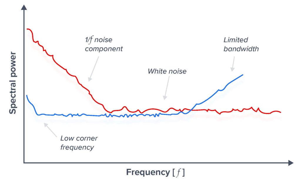
  • The noise spectra of two ADCs demonstrating noise increasing at high and low frequencies (1/f noise) along with a white noise level


    These effects are why many datasheets specify 1/f corner frequency for precision ICs, making it a critical specification to understand and measure effectively.

    How does 1/f noise affect measurements?

    Flicker noise can mask small signals and limit the resolution of instruments. Since it increases at low frequencies, it particularly affects long-term stability measurements and experiments where signals evolve slowly over time.

    For researchers and engineers, this means designing experiments and selecting instruments that can detect key DUT signals without being heavily impacted by flicker noise.

    1/f noise in physics

    In physics experiments, 1/f noise limits the sensitivity of detectors measuring weak signals, such as photodiodes in optical setups or superconducting devices in quantum research. Flicker noise can also appear in time-domain stability studies, making it harder to isolate true physical effects. This affects precision time standards like quartz oscillators, atomic clocks, and superconducting cavity resonators. Using measurements like Allan variance can help understand sources of instability.[5] Using a zero-dead-time, gapless event detector like a Time & Frequency Analyzer or Phasemeter to measure stability in real time can speed test throughput, in contrast to recording data and building all analysis in post-processing.

    1/f noise in electronics

    In electronics, 1/f noise is the dominant source of noise at low frequencies for amplifiers, sensors, and ADCs. Precision analog circuits, RF front ends, and MEMS devices are particularly vulnerable. Engineers often need to select components specifically rated for low flicker noise.

    1/f noise in signal processing

    When signals are digitized and analyzed, flicker noise can distort results, obscure weak signals, and complicate filtering requirements. Understanding the noise floor of your measurement system and knowing how much of it is due to 1/f contributions is crucial for accurate results.

    1/f noise in spectrum analyzers

    Spectrum analyzers are commonly used to observe noise across frequencies. However, at very low frequencies, their own internal noise can dominate, making it hard to distinguish between the instrument noise floor and the actual 1/f noise of the device under test. Finding a low-noise spectrum analyzer at low frequencies can be difficult and expensive.

    1/f noise in lock-in amplifiers

    Lock-in amplifiers are designed to extract weak signals from noisy environments, but flicker noise can complicate these measurements at low frequencies under a few hundred MHz. Since lock-ins operate at reference frequencies, 1/f noise near that frequency can directly degrade sensitivity.

    How to mitigate 1/f noise in test instruments

    To reduce the effect of 1/f noise at low frequencies, Moku:Pro and Moku:Delta each carry two sets of ADCs on every input channel. One ADC is optimized for low-speed, low-noise measurements. The other is selected for high speed and high performance, ensuring the user does not need to sacrifice bandwidth or accuracy at low frequencies. Signals from both ADCs are acquired simultaneously and blended to construct an optimal measurement signal.
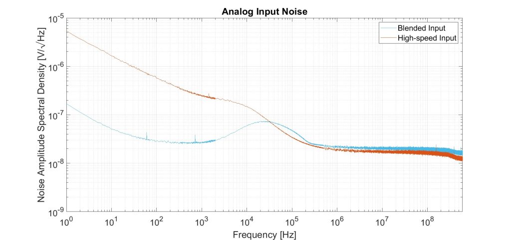
    Researchers studying precision electronics, RF systems, or fundamental physics can use Moku:Delta to characterize 1/f noise efficiently and reliably due to this dual ADC sampling. Embedded within Moku:Delta are 15 instruments that can be deployed standalone or as a system, allowing you to use the Spectrum Analyzer, Lock-in Amplifier, Oscilloscope, or Data Logger to measure and record results from your measurements.

    Another key strategy to accurately measure 1/f noise is a low resolution bandwidth and low minimum frequency in your spectrum analyzer. The Moku:Delta and Moku:Pro Spectrum Analyzers can observe signals down to 0 Hz, which is important for low-frequency noise characterization. These spectrum analyzers also allow the user to set a resolution bandwidth as low as 1 Hz, allowing you to accurately capture the 1/f noise without the effects of broadband noise obscuring results. A wider resolution bandwidth integrates more noise power, while a lower resolution bandwidth collects less noise power per resolution bin, leading to a lower displayed noise floor. By reducing the resolution bandwidth to 1 Hz, it is much easier to separate true 1/f characteristics from other noise sources. While 1/f noise is intrinsic to the device under test and measurement system, optimizing your measurement setup to accurately measure flicker noise can build a deeper understanding of the true performance of your device under test.

    Learn more about Moku:Delta here.

    FAQ

    Q: Is 1/f noise the same as flicker noise?

    A: Yes, both terms describe the same thing: low-frequency noise with a spectrum that decreases as frequency increases.

    Q: How is 1/f noise different from white noise?

    A: White noise has constant power across frequencies, while 1/f noise grows stronger at lower frequencies at about 3 dB/decade.

    Q: Where does flicker noise occur?

    A: In semiconductors, resistors, sensors, and even in natural systems outside of electronics.

    Q: How do you measure 1/f noise?

    A: Spectrum analyzers and lock-in amplifiers are common tools. Modern platforms like Moku:Delta combine these in one device, making measurement more efficient.

    References

    [1] “Pink noise,” Wikipedia, Nov. 07, 2020. https://en.wikipedia.org/wiki/Pink_noise

    ‌[2] “Understanding and Eliminating 1/f Noise | Analog Devices,” Analog.com, 2024. https://www.analog.com/en/resources/analog-dialogue/articles/understanding-and-eliminating-1-f-noise.html

    [3] “MT-048 TUTORIAL Op Amp Noise Relationships: 1/f Noise, RMS Noise, and Equivalent Noise Bandwidth.” Available: https://www.analog.com/media/en/training-seminars/tutorials/MT-048.pdf

    [4] “Fundamentals of Precision ADC Noise Analysis.” Accessed: Sep. 04, 2025. [Online]. Available: https://www.ti.com/lit/eb/slyy192a/slyy192a.pdf?ts=1757009681439

    [5] R. F. Voss, “1/f (Flicker) Noise: A Brief Review,” 33rd Annual Symposium on Frequency Control, Atlantic City, NJ, USA, 1979, pp. 40-46, doi: 10.1109/FREQ.1979.200297.

    [/vc_column_text][/vc_column][/vc_row]

  • For both ADCs and DACs, 1/f noise can degrade system accuracy in regards to timing.
  • The noise spectra of two ADCs demonstrating noise increasing at high and low frequencies (1/f noise) along with a white noise level


    These effects are why many datasheets specify 1/f corner frequency for precision ICs, making it a critical specification to understand and measure effectively.

    How does 1/f noise affect measurements?

    Flicker noise can mask small signals and limit the resolution of instruments. Since it increases at low frequencies, it particularly affects long-term stability measurements and experiments where signals evolve slowly over time.

    For researchers and engineers, this means designing experiments and selecting instruments that can detect key DUT signals without being heavily impacted by flicker noise.

    1/f noise in physics

    In physics experiments, 1/f noise limits the sensitivity of detectors measuring weak signals, such as photodiodes in optical setups or superconducting devices in quantum research. Flicker noise can also appear in time-domain stability studies, making it harder to isolate true physical effects. This affects precision time standards like quartz oscillators, atomic clocks, and superconducting cavity resonators. Using measurements like Allan variance can help understand sources of instability.[5] Using a zero-dead-time, gapless event detector like a Time & Frequency Analyzer or Phasemeter to measure stability in real time can speed test throughput, in contrast to recording data and building all analysis in post-processing.

    1/f noise in electronics

    In electronics, 1/f noise is the dominant source of noise at low frequencies for amplifiers, sensors, and ADCs. Precision analog circuits, RF front ends, and MEMS devices are particularly vulnerable. Engineers often need to select components specifically rated for low flicker noise.

    1/f noise in signal processing

    When signals are digitized and analyzed, flicker noise can distort results, obscure weak signals, and complicate filtering requirements. Understanding the noise floor of your measurement system and knowing how much of it is due to 1/f contributions is crucial for accurate results.

    1/f noise in spectrum analyzers

    Spectrum analyzers are commonly used to observe noise across frequencies. However, at very low frequencies, their own internal noise can dominate, making it hard to distinguish between the instrument noise floor and the actual 1/f noise of the device under test. Finding a low-noise spectrum analyzer at low frequencies can be difficult and expensive.

    1/f noise in lock-in amplifiers

    Lock-in amplifiers are designed to extract weak signals from noisy environments, but flicker noise can complicate these measurements at low frequencies under a few hundred MHz. Since lock-ins operate at reference frequencies, 1/f noise near that frequency can directly degrade sensitivity.

    How to mitigate 1/f noise in test instruments

    To reduce the effect of 1/f noise at low frequencies, Moku:Pro and Moku:Delta each carry two sets of ADCs on every input channel. One ADC is optimized for low-speed, low-noise measurements. The other is selected for high speed and high performance, ensuring the user does not need to sacrifice bandwidth or accuracy at low frequencies. Signals from both ADCs are acquired simultaneously and blended to construct an optimal measurement signal.

    Researchers studying precision electronics, RF systems, or fundamental physics can use Moku:Delta to characterize 1/f noise efficiently and reliably due to this dual ADC sampling. Embedded within Moku:Delta are 15 instruments that can be deployed standalone or as a system, allowing you to use the Spectrum Analyzer, Lock-in Amplifier, Oscilloscope, or Data Logger to measure and record results from your measurements.

    Another key strategy to accurately measure 1/f noise is a low resolution bandwidth and low minimum frequency in your spectrum analyzer. The Moku:Delta and Moku:Pro Spectrum Analyzers can observe signals down to 0 Hz, which is important for low-frequency noise characterization. These spectrum analyzers also allow the user to set a resolution bandwidth as low as 1 Hz, allowing you to accurately capture the 1/f noise without the effects of broadband noise obscuring results. A wider resolution bandwidth integrates more noise power, while a lower resolution bandwidth collects less noise power per resolution bin, leading to a lower displayed noise floor. By reducing the resolution bandwidth to 1 Hz, it is much easier to separate true 1/f characteristics from other noise sources. While 1/f noise is intrinsic to the device under test and measurement system, optimizing your measurement setup to accurately measure flicker noise can build a deeper understanding of the true performance of your device under test.

    Learn more about Moku:Delta here.

    FAQ

    Q: Is 1/f noise the same as flicker noise?

    A: Yes, both terms describe the same thing: low-frequency noise with a spectrum that decreases as frequency increases.

    Q: How is 1/f noise different from white noise?

    A: White noise has constant power across frequencies, while 1/f noise grows stronger at lower frequencies at about 3 dB/decade.

    Q: Where does flicker noise occur?

    A: In semiconductors, resistors, sensors, and even in natural systems outside of electronics.

    Q: How do you measure 1/f noise?

    A: Spectrum analyzers and lock-in amplifiers are common tools. Modern platforms like Moku:Delta combine these in one device, making measurement more efficient.

    References

    [1] “Pink noise,” Wikipedia, Nov. 07, 2020. https://en.wikipedia.org/wiki/Pink_noise

    ‌[2] “Understanding and Eliminating 1/f Noise | Analog Devices,” Analog.com, 2024. https://www.analog.com/en/resources/analog-dialogue/articles/understanding-and-eliminating-1-f-noise.html

    [3] “MT-048 TUTORIAL Op Amp Noise Relationships: 1/f Noise, RMS Noise, and Equivalent Noise Bandwidth.” Available: https://www.analog.com/media/en/training-seminars/tutorials/MT-048.pdf

    [4] “Fundamentals of Precision ADC Noise Analysis.” Accessed: Sep. 04, 2025. [Online]. Available: https://www.ti.com/lit/eb/slyy192a/slyy192a.pdf?ts=1757009681439

    [5] R. F. Voss, “1/f (Flicker) Noise: A Brief Review,” 33rd Annual Symposium on Frequency Control, Atlantic City, NJ, USA, 1979, pp. 40-46, doi: 10.1109/FREQ.1979.200297.

    [/vc_column_text][/vc_column][/vc_row]

  • Flicker noise can lead to low-frequency drift and offset instability.
  • The impact of 1/f noise on data converters (ADCs/DACs):[4]

      • In analog-to-digital converters (ADCs), flicker noise limits the effective number of bits (ENOB) at low input frequencies, leading to small signals getting buried in the noise floor.
      • In digital-to-analog converters (DACs), flicker noise can introduce spectral impurities and reduce linearity.
      • For both ADCs and DACs, 1/f noise can degrade system accuracy in regards to timing.
    The noise spectra of two ADCs demonstrating noise increasing at high and low frequencies (1/f noise) along with a white noise level


    These effects are why many datasheets specify 1/f corner frequency for precision ICs, making it a critical specification to understand and measure effectively.

    How does 1/f noise affect measurements?

    Flicker noise can mask small signals and limit the resolution of instruments. Since it increases at low frequencies, it particularly affects long-term stability measurements and experiments where signals evolve slowly over time.

    For researchers and engineers, this means designing experiments and selecting instruments that can detect key DUT signals without being heavily impacted by flicker noise.

    1/f noise in physics

    In physics experiments, 1/f noise limits the sensitivity of detectors measuring weak signals, such as photodiodes in optical setups or superconducting devices in quantum research. Flicker noise can also appear in time-domain stability studies, making it harder to isolate true physical effects. This affects precision time standards like quartz oscillators, atomic clocks, and superconducting cavity resonators. Using measurements like Allan variance can help understand sources of instability.[5] Using a zero-dead-time, gapless event detector like a Time & Frequency Analyzer or Phasemeter to measure stability in real time can speed test throughput, in contrast to recording data and building all analysis in post-processing.

    1/f noise in electronics

    In electronics, 1/f noise is the dominant source of noise at low frequencies for amplifiers, sensors, and ADCs. Precision analog circuits, RF front ends, and MEMS devices are particularly vulnerable. Engineers often need to select components specifically rated for low flicker noise.

    1/f noise in signal processing

    When signals are digitized and analyzed, flicker noise can distort results, obscure weak signals, and complicate filtering requirements. Understanding the noise floor of your measurement system and knowing how much of it is due to 1/f contributions is crucial for accurate results.

    1/f noise in spectrum analyzers

    Spectrum analyzers are commonly used to observe noise across frequencies. However, at very low frequencies, their own internal noise can dominate, making it hard to distinguish between the instrument noise floor and the actual 1/f noise of the device under test. Finding a low-noise spectrum analyzer at low frequencies can be difficult and expensive.

    1/f noise in lock-in amplifiers

    Lock-in amplifiers are designed to extract weak signals from noisy environments, but flicker noise can complicate these measurements at low frequencies under a few hundred MHz. Since lock-ins operate at reference frequencies, 1/f noise near that frequency can directly degrade sensitivity.

    How to mitigate 1/f noise in test instruments

    To reduce the effect of 1/f noise at low frequencies, Moku:Pro and Moku:Delta each carry two sets of ADCs on every input channel. One ADC is optimized for low-speed, low-noise measurements. The other is selected for high speed and high performance, ensuring the user does not need to sacrifice bandwidth or accuracy at low frequencies. Signals from both ADCs are acquired simultaneously and blended to construct an optimal measurement signal.

    Researchers studying precision electronics, RF systems, or fundamental physics can use Moku:Delta to characterize 1/f noise efficiently and reliably due to this dual ADC sampling. Embedded within Moku:Delta are 15 instruments that can be deployed standalone or as a system, allowing you to use the Spectrum Analyzer, Lock-in Amplifier, Oscilloscope, or Data Logger to measure and record results from your measurements.

    Another key strategy to accurately measure 1/f noise is a low resolution bandwidth and low minimum frequency in your spectrum analyzer. The Moku:Delta and Moku:Pro Spectrum Analyzers can observe signals down to 0 Hz, which is important for low-frequency noise characterization. These spectrum analyzers also allow the user to set a resolution bandwidth as low as 1 Hz, allowing you to accurately capture the 1/f noise without the effects of broadband noise obscuring results. A wider resolution bandwidth integrates more noise power, while a lower resolution bandwidth collects less noise power per resolution bin, leading to a lower displayed noise floor. By reducing the resolution bandwidth to 1 Hz, it is much easier to separate true 1/f characteristics from other noise sources. While 1/f noise is intrinsic to the device under test and measurement system, optimizing your measurement setup to accurately measure flicker noise can build a deeper understanding of the true performance of your device under test.

    Learn more about Moku:Delta here.

    FAQ

    Q: Is 1/f noise the same as flicker noise?

    A: Yes, both terms describe the same thing: low-frequency noise with a spectrum that decreases as frequency increases.

    Q: How is 1/f noise different from white noise?

    A: White noise has constant power across frequencies, while 1/f noise grows stronger at lower frequencies at about 3 dB/decade.

    Q: Where does flicker noise occur?

    A: In semiconductors, resistors, sensors, and even in natural systems outside of electronics.

    Q: How do you measure 1/f noise?

    A: Spectrum analyzers and lock-in amplifiers are common tools. Modern platforms like Moku:Delta combine these in one device, making measurement more efficient.

    References

    [1] “Pink noise,” Wikipedia, Nov. 07, 2020. https://en.wikipedia.org/wiki/Pink_noise

    ‌[2] “Understanding and Eliminating 1/f Noise | Analog Devices,” Analog.com, 2024. https://www.analog.com/en/resources/analog-dialogue/articles/understanding-and-eliminating-1-f-noise.html

    [3] “MT-048 TUTORIAL Op Amp Noise Relationships: 1/f Noise, RMS Noise, and Equivalent Noise Bandwidth.” Available: https://www.analog.com/media/en/training-seminars/tutorials/MT-048.pdf

    [4] “Fundamentals of Precision ADC Noise Analysis.” Accessed: Sep. 04, 2025. [Online]. Available: https://www.ti.com/lit/eb/slyy192a/slyy192a.pdf?ts=1757009681439

    [5] R. F. Voss, “1/f (Flicker) Noise: A Brief Review,” 33rd Annual Symposium on Frequency Control, Atlantic City, NJ, USA, 1979, pp. 40-46, doi: 10.1109/FREQ.1979.200297.

    [/vc_column_text][/vc_column][/vc_row]

  • Flicker noise can lead to low-frequency drift and offset instability.
  • The impact of 1/f noise on data converters (ADCs/DACs):[4]

      • In analog-to-digital converters (ADCs), flicker noise limits the effective number of bits (ENOB) at low input frequencies, leading to small signals getting buried in the noise floor.
      • In digital-to-analog converters (DACs), flicker noise can introduce spectral impurities and reduce linearity.
      • For both ADCs and DACs, 1/f noise can degrade system accuracy in regards to timing.
    The noise spectra of two ADCs demonstrating noise increasing at high and low frequencies (1/f noise) along with a white noise level


    These effects are why many datasheets specify 1/f corner frequency for precision ICs, making it a critical specification to understand and measure effectively.

    How does 1/f noise affect measurements?

    Flicker noise can mask small signals and limit the resolution of instruments. Since it increases at low frequencies, it particularly affects long-term stability measurements and experiments where signals evolve slowly over time.

    For researchers and engineers, this means designing experiments and selecting instruments that can detect key DUT signals without being heavily impacted by flicker noise.

    1/f noise in physics

    In physics experiments, 1/f noise limits the sensitivity of detectors measuring weak signals, such as photodiodes in optical setups or superconducting devices in quantum research. Flicker noise can also appear in time-domain stability studies, making it harder to isolate true physical effects. This affects precision time standards like quartz oscillators, atomic clocks, and superconducting cavity resonators. Using measurements like Allan variance can help understand sources of instability.[5] Using a zero-dead-time, gapless event detector like a Time & Frequency Analyzer or Phasemeter to measure stability in real time can speed test throughput, in contrast to recording data and building all analysis in post-processing.

    1/f noise in electronics

    In electronics, 1/f noise is the dominant source of noise at low frequencies for amplifiers, sensors, and ADCs. Precision analog circuits, RF front ends, and MEMS devices are particularly vulnerable. Engineers often need to select components specifically rated for low flicker noise.

    1/f noise in signal processing

    When signals are digitized and analyzed, flicker noise can distort results, obscure weak signals, and complicate filtering requirements. Understanding the noise floor of your measurement system and knowing how much of it is due to 1/f contributions is crucial for accurate results.

    1/f noise in spectrum analyzers

    Spectrum analyzers are commonly used to observe noise across frequencies. However, at very low frequencies, their own internal noise can dominate, making it hard to distinguish between the instrument noise floor and the actual 1/f noise of the device under test. Finding a low-noise spectrum analyzer at low frequencies can be difficult and expensive.

    1/f noise in lock-in amplifiers

    Lock-in amplifiers are designed to extract weak signals from noisy environments, but flicker noise can complicate these measurements at low frequencies under a few hundred MHz. Since lock-ins operate at reference frequencies, 1/f noise near that frequency can directly degrade sensitivity.

    How to mitigate 1/f noise in test instruments

    To reduce the effect of 1/f noise at low frequencies, Moku:Pro and Moku:Delta each carry two sets of ADCs on every input channel. One ADC is optimized for low-speed, low-noise measurements. The other is selected for high speed and high performance, ensuring the user does not need to sacrifice bandwidth or accuracy at low frequencies. Signals from both ADCs are acquired simultaneously and blended to construct an optimal measurement signal.

    Researchers studying precision electronics, RF systems, or fundamental physics can use Moku:Delta to characterize 1/f noise efficiently and reliably due to this dual ADC sampling. Embedded within Moku:Delta are 15 instruments that can be deployed standalone or as a system, allowing you to use the Spectrum Analyzer, Lock-in Amplifier, Oscilloscope, or Data Logger to measure and record results from your measurements.

    Another key strategy to accurately measure 1/f noise is a low resolution bandwidth and low minimum frequency in your spectrum analyzer. The Moku:Delta and Moku:Pro Spectrum Analyzers can observe signals down to 0 Hz, which is important for low-frequency noise characterization. These spectrum analyzers also allow the user to set a resolution bandwidth as low as 1 Hz, allowing you to accurately capture the 1/f noise without the effects of broadband noise obscuring results. A wider resolution bandwidth integrates more noise power, while a lower resolution bandwidth collects less noise power per resolution bin, leading to a lower displayed noise floor. By reducing the resolution bandwidth to 1 Hz, it is much easier to separate true 1/f characteristics from other noise sources. While 1/f noise is intrinsic to the device under test and measurement system, optimizing your measurement setup to accurately measure flicker noise can build a deeper understanding of the true performance of your device under test.

    Learn more about Moku:Delta here.

    FAQ

    Q: Is 1/f noise the same as flicker noise?

    A: Yes, both terms describe the same thing: low-frequency noise with a spectrum that decreases as frequency increases.

    Q: How is 1/f noise different from white noise?

    A: White noise has constant power across frequencies, while 1/f noise grows stronger at lower frequencies at about 3 dB/decade.

    Q: Where does flicker noise occur?

    A: In semiconductors, resistors, sensors, and even in natural systems outside of electronics.

    Q: How do you measure 1/f noise?

    A: Spectrum analyzers and lock-in amplifiers are common tools. Modern platforms like Moku:Delta combine these in one device, making measurement more efficient.

    References

    [1] “Pink noise,” Wikipedia, Nov. 07, 2020. https://en.wikipedia.org/wiki/Pink_noise

    ‌[2] “Understanding and Eliminating 1/f Noise | Analog Devices,” Analog.com, 2024. https://www.analog.com/en/resources/analog-dialogue/articles/understanding-and-eliminating-1-f-noise.html

    [3] “MT-048 TUTORIAL Op Amp Noise Relationships: 1/f Noise, RMS Noise, and Equivalent Noise Bandwidth.” Available: https://www.analog.com/media/en/training-seminars/tutorials/MT-048.pdf

    [4] “Fundamentals of Precision ADC Noise Analysis.” Accessed: Sep. 04, 2025. [Online]. Available: https://www.ti.com/lit/eb/slyy192a/slyy192a.pdf?ts=1757009681439

    [5] R. F. Voss, “1/f (Flicker) Noise: A Brief Review,” 33rd Annual Symposium on Frequency Control, Atlantic City, NJ, USA, 1979, pp. 40-46, doi: 10.1109/FREQ.1979.200297.

    [/vc_column_text][/vc_column][/vc_row]

    For common integrated circuits (ICs) like operational amplifiers (op-amps) and data converters, this can limit performance and introduce unwanted signal impurities.

    The impact of 1/f noise on op-amps:[3]

      • Since 1/f noise is most pronounced at low frequencies, the input stage of an op amp often sets the noise floor for the entire device.
      • Flicker noise can lead to low-frequency drift and offset instability.

    The impact of 1/f noise on data converters (ADCs/DACs):[4]

      • In analog-to-digital converters (ADCs), flicker noise limits the effective number of bits (ENOB) at low input frequencies, leading to small signals getting buried in the noise floor.
      • In digital-to-analog converters (DACs), flicker noise can introduce spectral impurities and reduce linearity.
      • For both ADCs and DACs, 1/f noise can degrade system accuracy in regards to timing.
    The noise spectra of two ADCs demonstrating noise increasing at high and low frequencies (1/f noise) along with a white noise level


    These effects are why many datasheets specify 1/f corner frequency for precision ICs, making it a critical specification to understand and measure effectively.

    How does 1/f noise affect measurements?

    Flicker noise can mask small signals and limit the resolution of instruments. Since it increases at low frequencies, it particularly affects long-term stability measurements and experiments where signals evolve slowly over time.

    For researchers and engineers, this means designing experiments and selecting instruments that can detect key DUT signals without being heavily impacted by flicker noise.

    1/f noise in physics

    In physics experiments, 1/f noise limits the sensitivity of detectors measuring weak signals, such as photodiodes in optical setups or superconducting devices in quantum research. Flicker noise can also appear in time-domain stability studies, making it harder to isolate true physical effects. This affects precision time standards like quartz oscillators, atomic clocks, and superconducting cavity resonators. Using measurements like Allan variance can help understand sources of instability.[5] Using a zero-dead-time, gapless event detector like a Time & Frequency Analyzer or Phasemeter to measure stability in real time can speed test throughput, in contrast to recording data and building all analysis in post-processing.

    1/f noise in electronics

    In electronics, 1/f noise is the dominant source of noise at low frequencies for amplifiers, sensors, and ADCs. Precision analog circuits, RF front ends, and MEMS devices are particularly vulnerable. Engineers often need to select components specifically rated for low flicker noise.

    1/f noise in signal processing

    When signals are digitized and analyzed, flicker noise can distort results, obscure weak signals, and complicate filtering requirements. Understanding the noise floor of your measurement system and knowing how much of it is due to 1/f contributions is crucial for accurate results.

    1/f noise in spectrum analyzers

    Spectrum analyzers are commonly used to observe noise across frequencies. However, at very low frequencies, their own internal noise can dominate, making it hard to distinguish between the instrument noise floor and the actual 1/f noise of the device under test. Finding a low-noise spectrum analyzer at low frequencies can be difficult and expensive.

    1/f noise in lock-in amplifiers

    Lock-in amplifiers are designed to extract weak signals from noisy environments, but flicker noise can complicate these measurements at low frequencies under a few hundred MHz. Since lock-ins operate at reference frequencies, 1/f noise near that frequency can directly degrade sensitivity.

    How to mitigate 1/f noise in test instruments

    To reduce the effect of 1/f noise at low frequencies, Moku:Pro and Moku:Delta each carry two sets of ADCs on every input channel. One ADC is optimized for low-speed, low-noise measurements. The other is selected for high speed and high performance, ensuring the user does not need to sacrifice bandwidth or accuracy at low frequencies. Signals from both ADCs are acquired simultaneously and blended to construct an optimal measurement signal.

    Researchers studying precision electronics, RF systems, or fundamental physics can use Moku:Delta to characterize 1/f noise efficiently and reliably due to this dual ADC sampling. Embedded within Moku:Delta are 15 instruments that can be deployed standalone or as a system, allowing you to use the Spectrum Analyzer, Lock-in Amplifier, Oscilloscope, or Data Logger to measure and record results from your measurements.

    Another key strategy to accurately measure 1/f noise is a low resolution bandwidth and low minimum frequency in your spectrum analyzer. The Moku:Delta and Moku:Pro Spectrum Analyzers can observe signals down to 0 Hz, which is important for low-frequency noise characterization. These spectrum analyzers also allow the user to set a resolution bandwidth as low as 1 Hz, allowing you to accurately capture the 1/f noise without the effects of broadband noise obscuring results. A wider resolution bandwidth integrates more noise power, while a lower resolution bandwidth collects less noise power per resolution bin, leading to a lower displayed noise floor. By reducing the resolution bandwidth to 1 Hz, it is much easier to separate true 1/f characteristics from other noise sources. While 1/f noise is intrinsic to the device under test and measurement system, optimizing your measurement setup to accurately measure flicker noise can build a deeper understanding of the true performance of your device under test.

    Learn more about Moku:Delta here.

    FAQ

    Q: Is 1/f noise the same as flicker noise?

    A: Yes, both terms describe the same thing: low-frequency noise with a spectrum that decreases as frequency increases.

    Q: How is 1/f noise different from white noise?

    A: White noise has constant power across frequencies, while 1/f noise grows stronger at lower frequencies at about 3 dB/decade.

    Q: Where does flicker noise occur?

    A: In semiconductors, resistors, sensors, and even in natural systems outside of electronics.

    Q: How do you measure 1/f noise?

    A: Spectrum analyzers and lock-in amplifiers are common tools. Modern platforms like Moku:Delta combine these in one device, making measurement more efficient.

    References

    [1] “Pink noise,” Wikipedia, Nov. 07, 2020. https://en.wikipedia.org/wiki/Pink_noise

    ‌[2] “Understanding and Eliminating 1/f Noise | Analog Devices,” Analog.com, 2024. https://www.analog.com/en/resources/analog-dialogue/articles/understanding-and-eliminating-1-f-noise.html

    [3] “MT-048 TUTORIAL Op Amp Noise Relationships: 1/f Noise, RMS Noise, and Equivalent Noise Bandwidth.” Available: https://www.analog.com/media/en/training-seminars/tutorials/MT-048.pdf

    [4] “Fundamentals of Precision ADC Noise Analysis.” Accessed: Sep. 04, 2025. [Online]. Available: https://www.ti.com/lit/eb/slyy192a/slyy192a.pdf?ts=1757009681439

    [5] R. F. Voss, “1/f (Flicker) Noise: A Brief Review,” 33rd Annual Symposium on Frequency Control, Atlantic City, NJ, USA, 1979, pp. 40-46, doi: 10.1109/FREQ.1979.200297.

    [/vc_column_text][/vc_column][/vc_row]

    In semiconductor devices like MOSFETs and BJTs, flicker noise originates from charge trapping and detrapping at defects near the oxide-semiconductor interface or from fluctuations in carrier mobility. This makes it especially problematic at low frequencies, where it can dominate over thermal noise.

    For common integrated circuits (ICs) like operational amplifiers (op-amps) and data converters, this can limit performance and introduce unwanted signal impurities.

    The impact of 1/f noise on op-amps:[3]

      • Since 1/f noise is most pronounced at low frequencies, the input stage of an op amp often sets the noise floor for the entire device.
      • Flicker noise can lead to low-frequency drift and offset instability.

    The impact of 1/f noise on data converters (ADCs/DACs):[4]

      • In analog-to-digital converters (ADCs), flicker noise limits the effective number of bits (ENOB) at low input frequencies, leading to small signals getting buried in the noise floor.
      • In digital-to-analog converters (DACs), flicker noise can introduce spectral impurities and reduce linearity.
      • For both ADCs and DACs, 1/f noise can degrade system accuracy in regards to timing.
    The noise spectra of two ADCs demonstrating noise increasing at high and low frequencies (1/f noise) along with a white noise level


    These effects are why many datasheets specify 1/f corner frequency for precision ICs, making it a critical specification to understand and measure effectively.

    How does 1/f noise affect measurements?

    Flicker noise can mask small signals and limit the resolution of instruments. Since it increases at low frequencies, it particularly affects long-term stability measurements and experiments where signals evolve slowly over time.

    For researchers and engineers, this means designing experiments and selecting instruments that can detect key DUT signals without being heavily impacted by flicker noise.

    1/f noise in physics

    In physics experiments, 1/f noise limits the sensitivity of detectors measuring weak signals, such as photodiodes in optical setups or superconducting devices in quantum research. Flicker noise can also appear in time-domain stability studies, making it harder to isolate true physical effects. This affects precision time standards like quartz oscillators, atomic clocks, and superconducting cavity resonators. Using measurements like Allan variance can help understand sources of instability.[5] Using a zero-dead-time, gapless event detector like a Time & Frequency Analyzer or Phasemeter to measure stability in real time can speed test throughput, in contrast to recording data and building all analysis in post-processing.

    1/f noise in electronics

    In electronics, 1/f noise is the dominant source of noise at low frequencies for amplifiers, sensors, and ADCs. Precision analog circuits, RF front ends, and MEMS devices are particularly vulnerable. Engineers often need to select components specifically rated for low flicker noise.

    1/f noise in signal processing

    When signals are digitized and analyzed, flicker noise can distort results, obscure weak signals, and complicate filtering requirements. Understanding the noise floor of your measurement system and knowing how much of it is due to 1/f contributions is crucial for accurate results.

    1/f noise in spectrum analyzers

    Spectrum analyzers are commonly used to observe noise across frequencies. However, at very low frequencies, their own internal noise can dominate, making it hard to distinguish between the instrument noise floor and the actual 1/f noise of the device under test. Finding a low-noise spectrum analyzer at low frequencies can be difficult and expensive.

    1/f noise in lock-in amplifiers

    Lock-in amplifiers are designed to extract weak signals from noisy environments, but flicker noise can complicate these measurements at low frequencies under a few hundred MHz. Since lock-ins operate at reference frequencies, 1/f noise near that frequency can directly degrade sensitivity.

    How to mitigate 1/f noise in test instruments

    To reduce the effect of 1/f noise at low frequencies, Moku:Pro and Moku:Delta each carry two sets of ADCs on every input channel. One ADC is optimized for low-speed, low-noise measurements. The other is selected for high speed and high performance, ensuring the user does not need to sacrifice bandwidth or accuracy at low frequencies. Signals from both ADCs are acquired simultaneously and blended to construct an optimal measurement signal.

    Researchers studying precision electronics, RF systems, or fundamental physics can use Moku:Delta to characterize 1/f noise efficiently and reliably due to this dual ADC sampling. Embedded within Moku:Delta are 15 instruments that can be deployed standalone or as a system, allowing you to use the Spectrum Analyzer, Lock-in Amplifier, Oscilloscope, or Data Logger to measure and record results from your measurements.

    Another key strategy to accurately measure 1/f noise is a low resolution bandwidth and low minimum frequency in your spectrum analyzer. The Moku:Delta and Moku:Pro Spectrum Analyzers can observe signals down to 0 Hz, which is important for low-frequency noise characterization. These spectrum analyzers also allow the user to set a resolution bandwidth as low as 1 Hz, allowing you to accurately capture the 1/f noise without the effects of broadband noise obscuring results. A wider resolution bandwidth integrates more noise power, while a lower resolution bandwidth collects less noise power per resolution bin, leading to a lower displayed noise floor. By reducing the resolution bandwidth to 1 Hz, it is much easier to separate true 1/f characteristics from other noise sources. While 1/f noise is intrinsic to the device under test and measurement system, optimizing your measurement setup to accurately measure flicker noise can build a deeper understanding of the true performance of your device under test.

    Learn more about Moku:Delta here.

    FAQ

    Q: Is 1/f noise the same as flicker noise?

    A: Yes, both terms describe the same thing: low-frequency noise with a spectrum that decreases as frequency increases.

    Q: How is 1/f noise different from white noise?

    A: White noise has constant power across frequencies, while 1/f noise grows stronger at lower frequencies at about 3 dB/decade.

    Q: Where does flicker noise occur?

    A: In semiconductors, resistors, sensors, and even in natural systems outside of electronics.

    Q: How do you measure 1/f noise?

    A: Spectrum analyzers and lock-in amplifiers are common tools. Modern platforms like Moku:Delta combine these in one device, making measurement more efficient.

    References

    [1] “Pink noise,” Wikipedia, Nov. 07, 2020. https://en.wikipedia.org/wiki/Pink_noise

    ‌[2] “Understanding and Eliminating 1/f Noise | Analog Devices,” Analog.com, 2024. https://www.analog.com/en/resources/analog-dialogue/articles/understanding-and-eliminating-1-f-noise.html

    [3] “MT-048 TUTORIAL Op Amp Noise Relationships: 1/f Noise, RMS Noise, and Equivalent Noise Bandwidth.” Available: https://www.analog.com/media/en/training-seminars/tutorials/MT-048.pdf

    [4] “Fundamentals of Precision ADC Noise Analysis.” Accessed: Sep. 04, 2025. [Online]. Available: https://www.ti.com/lit/eb/slyy192a/slyy192a.pdf?ts=1757009681439

    [5] R. F. Voss, “1/f (Flicker) Noise: A Brief Review,” 33rd Annual Symposium on Frequency Control, Atlantic City, NJ, USA, 1979, pp. 40-46, doi: 10.1109/FREQ.1979.200297.

    [/vc_column_text][/vc_column][/vc_row]

    This type of noise is distinct from white noise, which has equal power across all frequencies, and thermal noise, which is primarily determined by temperature.

    What causes 1/f noise?

    Semiconductor 1/f noise

    In semiconductor devices like MOSFETs and BJTs, flicker noise originates from charge trapping and detrapping at defects near the oxide-semiconductor interface or from fluctuations in carrier mobility. This makes it especially problematic at low frequencies, where it can dominate over thermal noise.

    For common integrated circuits (ICs) like operational amplifiers (op-amps) and data converters, this can limit performance and introduce unwanted signal impurities.

    The impact of 1/f noise on op-amps:[3]

      • Since 1/f noise is most pronounced at low frequencies, the input stage of an op amp often sets the noise floor for the entire device.
      • Flicker noise can lead to low-frequency drift and offset instability.

    The impact of 1/f noise on data converters (ADCs/DACs):[4]

      • In analog-to-digital converters (ADCs), flicker noise limits the effective number of bits (ENOB) at low input frequencies, leading to small signals getting buried in the noise floor.
      • In digital-to-analog converters (DACs), flicker noise can introduce spectral impurities and reduce linearity.
      • For both ADCs and DACs, 1/f noise can degrade system accuracy in regards to timing.
    The noise spectra of two ADCs demonstrating noise increasing at high and low frequencies (1/f noise) along with a white noise level


    These effects are why many datasheets specify 1/f corner frequency for precision ICs, making it a critical specification to understand and measure effectively.

    How does 1/f noise affect measurements?

    Flicker noise can mask small signals and limit the resolution of instruments. Since it increases at low frequencies, it particularly affects long-term stability measurements and experiments where signals evolve slowly over time.

    For researchers and engineers, this means designing experiments and selecting instruments that can detect key DUT signals without being heavily impacted by flicker noise.

    1/f noise in physics

    In physics experiments, 1/f noise limits the sensitivity of detectors measuring weak signals, such as photodiodes in optical setups or superconducting devices in quantum research. Flicker noise can also appear in time-domain stability studies, making it harder to isolate true physical effects. This affects precision time standards like quartz oscillators, atomic clocks, and superconducting cavity resonators. Using measurements like Allan variance can help understand sources of instability.[5] Using a zero-dead-time, gapless event detector like a Time & Frequency Analyzer or Phasemeter to measure stability in real time can speed test throughput, in contrast to recording data and building all analysis in post-processing.

    1/f noise in electronics

    In electronics, 1/f noise is the dominant source of noise at low frequencies for amplifiers, sensors, and ADCs. Precision analog circuits, RF front ends, and MEMS devices are particularly vulnerable. Engineers often need to select components specifically rated for low flicker noise.

    1/f noise in signal processing

    When signals are digitized and analyzed, flicker noise can distort results, obscure weak signals, and complicate filtering requirements. Understanding the noise floor of your measurement system and knowing how much of it is due to 1/f contributions is crucial for accurate results.

    1/f noise in spectrum analyzers

    Spectrum analyzers are commonly used to observe noise across frequencies. However, at very low frequencies, their own internal noise can dominate, making it hard to distinguish between the instrument noise floor and the actual 1/f noise of the device under test. Finding a low-noise spectrum analyzer at low frequencies can be difficult and expensive.

    1/f noise in lock-in amplifiers

    Lock-in amplifiers are designed to extract weak signals from noisy environments, but flicker noise can complicate these measurements at low frequencies under a few hundred MHz. Since lock-ins operate at reference frequencies, 1/f noise near that frequency can directly degrade sensitivity.

    How to mitigate 1/f noise in test instruments

    To reduce the effect of 1/f noise at low frequencies, Moku:Pro and Moku:Delta each carry two sets of ADCs on every input channel. One ADC is optimized for low-speed, low-noise measurements. The other is selected for high speed and high performance, ensuring the user does not need to sacrifice bandwidth or accuracy at low frequencies. Signals from both ADCs are acquired simultaneously and blended to construct an optimal measurement signal.

    Researchers studying precision electronics, RF systems, or fundamental physics can use Moku:Delta to characterize 1/f noise efficiently and reliably due to this dual ADC sampling. Embedded within Moku:Delta are 15 instruments that can be deployed standalone or as a system, allowing you to use the Spectrum Analyzer, Lock-in Amplifier, Oscilloscope, or Data Logger to measure and record results from your measurements.

    Another key strategy to accurately measure 1/f noise is a low resolution bandwidth and low minimum frequency in your spectrum analyzer. The Moku:Delta and Moku:Pro Spectrum Analyzers can observe signals down to 0 Hz, which is important for low-frequency noise characterization. These spectrum analyzers also allow the user to set a resolution bandwidth as low as 1 Hz, allowing you to accurately capture the 1/f noise without the effects of broadband noise obscuring results. A wider resolution bandwidth integrates more noise power, while a lower resolution bandwidth collects less noise power per resolution bin, leading to a lower displayed noise floor. By reducing the resolution bandwidth to 1 Hz, it is much easier to separate true 1/f characteristics from other noise sources. While 1/f noise is intrinsic to the device under test and measurement system, optimizing your measurement setup to accurately measure flicker noise can build a deeper understanding of the true performance of your device under test.

    Learn more about Moku:Delta here.

    FAQ

    Q: Is 1/f noise the same as flicker noise?

    A: Yes, both terms describe the same thing: low-frequency noise with a spectrum that decreases as frequency increases.

    Q: How is 1/f noise different from white noise?

    A: White noise has constant power across frequencies, while 1/f noise grows stronger at lower frequencies at about 3 dB/decade.

    Q: Where does flicker noise occur?

    A: In semiconductors, resistors, sensors, and even in natural systems outside of electronics.

    Q: How do you measure 1/f noise?

    A: Spectrum analyzers and lock-in amplifiers are common tools. Modern platforms like Moku:Delta combine these in one device, making measurement more efficient.

    References

    [1] “Pink noise,” Wikipedia, Nov. 07, 2020. https://en.wikipedia.org/wiki/Pink_noise

    ‌[2] “Understanding and Eliminating 1/f Noise | Analog Devices,” Analog.com, 2024. https://www.analog.com/en/resources/analog-dialogue/articles/understanding-and-eliminating-1-f-noise.html

    [3] “MT-048 TUTORIAL Op Amp Noise Relationships: 1/f Noise, RMS Noise, and Equivalent Noise Bandwidth.” Available: https://www.analog.com/media/en/training-seminars/tutorials/MT-048.pdf

    [4] “Fundamentals of Precision ADC Noise Analysis.” Accessed: Sep. 04, 2025. [Online]. Available: https://www.ti.com/lit/eb/slyy192a/slyy192a.pdf?ts=1757009681439

    [5] R. F. Voss, “1/f (Flicker) Noise: A Brief Review,” 33rd Annual Symposium on Frequency Control, Atlantic City, NJ, USA, 1979, pp. 40-46, doi: 10.1109/FREQ.1979.200297.

    [/vc_column_text][/vc_column][/vc_row]

  • Pink noise
  • This type of noise is distinct from white noise, which has equal power across all frequencies, and thermal noise, which is primarily determined by temperature.

    What causes 1/f noise?

    Semiconductor 1/f noise

    In semiconductor devices like MOSFETs and BJTs, flicker noise originates from charge trapping and detrapping at defects near the oxide-semiconductor interface or from fluctuations in carrier mobility. This makes it especially problematic at low frequencies, where it can dominate over thermal noise.

    For common integrated circuits (ICs) like operational amplifiers (op-amps) and data converters, this can limit performance and introduce unwanted signal impurities.

    The impact of 1/f noise on op-amps:[3]

      • Since 1/f noise is most pronounced at low frequencies, the input stage of an op amp often sets the noise floor for the entire device.
      • Flicker noise can lead to low-frequency drift and offset instability.

    The impact of 1/f noise on data converters (ADCs/DACs):[4]

      • In analog-to-digital converters (ADCs), flicker noise limits the effective number of bits (ENOB) at low input frequencies, leading to small signals getting buried in the noise floor.
      • In digital-to-analog converters (DACs), flicker noise can introduce spectral impurities and reduce linearity.
      • For both ADCs and DACs, 1/f noise can degrade system accuracy in regards to timing.
    The noise spectra of two ADCs demonstrating noise increasing at high and low frequencies (1/f noise) along with a white noise level


    These effects are why many datasheets specify 1/f corner frequency for precision ICs, making it a critical specification to understand and measure effectively.

    How does 1/f noise affect measurements?

    Flicker noise can mask small signals and limit the resolution of instruments. Since it increases at low frequencies, it particularly affects long-term stability measurements and experiments where signals evolve slowly over time.

    For researchers and engineers, this means designing experiments and selecting instruments that can detect key DUT signals without being heavily impacted by flicker noise.

    1/f noise in physics

    In physics experiments, 1/f noise limits the sensitivity of detectors measuring weak signals, such as photodiodes in optical setups or superconducting devices in quantum research. Flicker noise can also appear in time-domain stability studies, making it harder to isolate true physical effects. This affects precision time standards like quartz oscillators, atomic clocks, and superconducting cavity resonators. Using measurements like Allan variance can help understand sources of instability.[5] Using a zero-dead-time, gapless event detector like a Time & Frequency Analyzer or Phasemeter to measure stability in real time can speed test throughput, in contrast to recording data and building all analysis in post-processing.

    1/f noise in electronics

    In electronics, 1/f noise is the dominant source of noise at low frequencies for amplifiers, sensors, and ADCs. Precision analog circuits, RF front ends, and MEMS devices are particularly vulnerable. Engineers often need to select components specifically rated for low flicker noise.

    1/f noise in signal processing

    When signals are digitized and analyzed, flicker noise can distort results, obscure weak signals, and complicate filtering requirements. Understanding the noise floor of your measurement system and knowing how much of it is due to 1/f contributions is crucial for accurate results.

    1/f noise in spectrum analyzers

    Spectrum analyzers are commonly used to observe noise across frequencies. However, at very low frequencies, their own internal noise can dominate, making it hard to distinguish between the instrument noise floor and the actual 1/f noise of the device under test. Finding a low-noise spectrum analyzer at low frequencies can be difficult and expensive.

    1/f noise in lock-in amplifiers

    Lock-in amplifiers are designed to extract weak signals from noisy environments, but flicker noise can complicate these measurements at low frequencies under a few hundred MHz. Since lock-ins operate at reference frequencies, 1/f noise near that frequency can directly degrade sensitivity.

    How to mitigate 1/f noise in test instruments

    To reduce the effect of 1/f noise at low frequencies, Moku:Pro and Moku:Delta each carry two sets of ADCs on every input channel. One ADC is optimized for low-speed, low-noise measurements. The other is selected for high speed and high performance, ensuring the user does not need to sacrifice bandwidth or accuracy at low frequencies. Signals from both ADCs are acquired simultaneously and blended to construct an optimal measurement signal.

    Researchers studying precision electronics, RF systems, or fundamental physics can use Moku:Delta to characterize 1/f noise efficiently and reliably due to this dual ADC sampling. Embedded within Moku:Delta are 15 instruments that can be deployed standalone or as a system, allowing you to use the Spectrum Analyzer, Lock-in Amplifier, Oscilloscope, or Data Logger to measure and record results from your measurements.

    Another key strategy to accurately measure 1/f noise is a low resolution bandwidth and low minimum frequency in your spectrum analyzer. The Moku:Delta and Moku:Pro Spectrum Analyzers can observe signals down to 0 Hz, which is important for low-frequency noise characterization. These spectrum analyzers also allow the user to set a resolution bandwidth as low as 1 Hz, allowing you to accurately capture the 1/f noise without the effects of broadband noise obscuring results. A wider resolution bandwidth integrates more noise power, while a lower resolution bandwidth collects less noise power per resolution bin, leading to a lower displayed noise floor. By reducing the resolution bandwidth to 1 Hz, it is much easier to separate true 1/f characteristics from other noise sources. While 1/f noise is intrinsic to the device under test and measurement system, optimizing your measurement setup to accurately measure flicker noise can build a deeper understanding of the true performance of your device under test.

    Learn more about Moku:Delta here.

    FAQ

    Q: Is 1/f noise the same as flicker noise?

    A: Yes, both terms describe the same thing: low-frequency noise with a spectrum that decreases as frequency increases.

    Q: How is 1/f noise different from white noise?

    A: White noise has constant power across frequencies, while 1/f noise grows stronger at lower frequencies at about 3 dB/decade.

    Q: Where does flicker noise occur?

    A: In semiconductors, resistors, sensors, and even in natural systems outside of electronics.

    Q: How do you measure 1/f noise?

    A: Spectrum analyzers and lock-in amplifiers are common tools. Modern platforms like Moku:Delta combine these in one device, making measurement more efficient.

    References

    [1] “Pink noise,” Wikipedia, Nov. 07, 2020. https://en.wikipedia.org/wiki/Pink_noise

    ‌[2] “Understanding and Eliminating 1/f Noise | Analog Devices,” Analog.com, 2024. https://www.analog.com/en/resources/analog-dialogue/articles/understanding-and-eliminating-1-f-noise.html

    [3] “MT-048 TUTORIAL Op Amp Noise Relationships: 1/f Noise, RMS Noise, and Equivalent Noise Bandwidth.” Available: https://www.analog.com/media/en/training-seminars/tutorials/MT-048.pdf

    [4] “Fundamentals of Precision ADC Noise Analysis.” Accessed: Sep. 04, 2025. [Online]. Available: https://www.ti.com/lit/eb/slyy192a/slyy192a.pdf?ts=1757009681439

    [5] R. F. Voss, “1/f (Flicker) Noise: A Brief Review,” 33rd Annual Symposium on Frequency Control, Atlantic City, NJ, USA, 1979, pp. 40-46, doi: 10.1109/FREQ.1979.200297.

    [/vc_column_text][/vc_column][/vc_row]

  • Pink noise
  • This type of noise is distinct from white noise, which has equal power across all frequencies, and thermal noise, which is primarily determined by temperature.

    What causes 1/f noise?

    Semiconductor 1/f noise

    In semiconductor devices like MOSFETs and BJTs, flicker noise originates from charge trapping and detrapping at defects near the oxide-semiconductor interface or from fluctuations in carrier mobility. This makes it especially problematic at low frequencies, where it can dominate over thermal noise.

    For common integrated circuits (ICs) like operational amplifiers (op-amps) and data converters, this can limit performance and introduce unwanted signal impurities.

    The impact of 1/f noise on op-amps:[3]

      • Since 1/f noise is most pronounced at low frequencies, the input stage of an op amp often sets the noise floor for the entire device.
      • Flicker noise can lead to low-frequency drift and offset instability.

    The impact of 1/f noise on data converters (ADCs/DACs):[4]

      • In analog-to-digital converters (ADCs), flicker noise limits the effective number of bits (ENOB) at low input frequencies, leading to small signals getting buried in the noise floor.
      • In digital-to-analog converters (DACs), flicker noise can introduce spectral impurities and reduce linearity.
      • For both ADCs and DACs, 1/f noise can degrade system accuracy in regards to timing.
    The noise spectra of two ADCs demonstrating noise increasing at high and low frequencies (1/f noise) along with a white noise level


    These effects are why many datasheets specify 1/f corner frequency for precision ICs, making it a critical specification to understand and measure effectively.

    How does 1/f noise affect measurements?

    Flicker noise can mask small signals and limit the resolution of instruments. Since it increases at low frequencies, it particularly affects long-term stability measurements and experiments where signals evolve slowly over time.

    For researchers and engineers, this means designing experiments and selecting instruments that can detect key DUT signals without being heavily impacted by flicker noise.

    1/f noise in physics

    In physics experiments, 1/f noise limits the sensitivity of detectors measuring weak signals, such as photodiodes in optical setups or superconducting devices in quantum research. Flicker noise can also appear in time-domain stability studies, making it harder to isolate true physical effects. This affects precision time standards like quartz oscillators, atomic clocks, and superconducting cavity resonators. Using measurements like Allan variance can help understand sources of instability.[5] Using a zero-dead-time, gapless event detector like a Time & Frequency Analyzer or Phasemeter to measure stability in real time can speed test throughput, in contrast to recording data and building all analysis in post-processing.

    1/f noise in electronics

    In electronics, 1/f noise is the dominant source of noise at low frequencies for amplifiers, sensors, and ADCs. Precision analog circuits, RF front ends, and MEMS devices are particularly vulnerable. Engineers often need to select components specifically rated for low flicker noise.

    1/f noise in signal processing

    When signals are digitized and analyzed, flicker noise can distort results, obscure weak signals, and complicate filtering requirements. Understanding the noise floor of your measurement system and knowing how much of it is due to 1/f contributions is crucial for accurate results.

    1/f noise in spectrum analyzers

    Spectrum analyzers are commonly used to observe noise across frequencies. However, at very low frequencies, their own internal noise can dominate, making it hard to distinguish between the instrument noise floor and the actual 1/f noise of the device under test. Finding a low-noise spectrum analyzer at low frequencies can be difficult and expensive.

    1/f noise in lock-in amplifiers

    Lock-in amplifiers are designed to extract weak signals from noisy environments, but flicker noise can complicate these measurements at low frequencies under a few hundred MHz. Since lock-ins operate at reference frequencies, 1/f noise near that frequency can directly degrade sensitivity.

    How to mitigate 1/f noise in test instruments

    To reduce the effect of 1/f noise at low frequencies, Moku:Pro and Moku:Delta each carry two sets of ADCs on every input channel. One ADC is optimized for low-speed, low-noise measurements. The other is selected for high speed and high performance, ensuring the user does not need to sacrifice bandwidth or accuracy at low frequencies. Signals from both ADCs are acquired simultaneously and blended to construct an optimal measurement signal.

    Researchers studying precision electronics, RF systems, or fundamental physics can use Moku:Delta to characterize 1/f noise efficiently and reliably due to this dual ADC sampling. Embedded within Moku:Delta are 15 instruments that can be deployed standalone or as a system, allowing you to use the Spectrum Analyzer, Lock-in Amplifier, Oscilloscope, or Data Logger to measure and record results from your measurements.

    Another key strategy to accurately measure 1/f noise is a low resolution bandwidth and low minimum frequency in your spectrum analyzer. The Moku:Delta and Moku:Pro Spectrum Analyzers can observe signals down to 0 Hz, which is important for low-frequency noise characterization. These spectrum analyzers also allow the user to set a resolution bandwidth as low as 1 Hz, allowing you to accurately capture the 1/f noise without the effects of broadband noise obscuring results. A wider resolution bandwidth integrates more noise power, while a lower resolution bandwidth collects less noise power per resolution bin, leading to a lower displayed noise floor. By reducing the resolution bandwidth to 1 Hz, it is much easier to separate true 1/f characteristics from other noise sources. While 1/f noise is intrinsic to the device under test and measurement system, optimizing your measurement setup to accurately measure flicker noise can build a deeper understanding of the true performance of your device under test.

    Learn more about Moku:Delta here.

    FAQ

    Q: Is 1/f noise the same as flicker noise?

    A: Yes, both terms describe the same thing: low-frequency noise with a spectrum that decreases as frequency increases.

    Q: How is 1/f noise different from white noise?

    A: White noise has constant power across frequencies, while 1/f noise grows stronger at lower frequencies at about 3 dB/decade.

    Q: Where does flicker noise occur?

    A: In semiconductors, resistors, sensors, and even in natural systems outside of electronics.

    Q: How do you measure 1/f noise?

    A: Spectrum analyzers and lock-in amplifiers are common tools. Modern platforms like Moku:Delta combine these in one device, making measurement more efficient.

    References

    [1] “Pink noise,” Wikipedia, Nov. 07, 2020. https://en.wikipedia.org/wiki/Pink_noise

    ‌[2] “Understanding and Eliminating 1/f Noise | Analog Devices,” Analog.com, 2024. https://www.analog.com/en/resources/analog-dialogue/articles/understanding-and-eliminating-1-f-noise.html

    [3] “MT-048 TUTORIAL Op Amp Noise Relationships: 1/f Noise, RMS Noise, and Equivalent Noise Bandwidth.” Available: https://www.analog.com/media/en/training-seminars/tutorials/MT-048.pdf

    [4] “Fundamentals of Precision ADC Noise Analysis.” Accessed: Sep. 04, 2025. [Online]. Available: https://www.ti.com/lit/eb/slyy192a/slyy192a.pdf?ts=1757009681439

    [5] R. F. Voss, “1/f (Flicker) Noise: A Brief Review,” 33rd Annual Symposium on Frequency Control, Atlantic City, NJ, USA, 1979, pp. 40-46, doi: 10.1109/FREQ.1979.200297.

    [/vc_column_text][/vc_column][/vc_row]

    Introduction to 1/f noise

    1/f noise, also known as flicker noise or pink noise[1], is a type of low-frequency noise that increases in strength as frequency decreases. It shows up in semiconductors, resistors, sensors, and even natural systems, and it can limit the performance of precision electronics like ADCs, RF circuits, and oscillators. Unlike white noise, which has equal power at all frequencies, 1/f noise dominates at low frequencies and is harder to measure. Traditional spectrum analyzers and lock-in amplifiers are commonly used to measure 1/f noise, but capturing meaningful data requires long integration times. The measurement instrument must have an exceptionally high dynamic range to capture small variations while reaching frequencies low enough to accurately capture flicker noise. Many spectrum analyzers only reach minimum frequencies in the kHz range, requiring semiconductor test engineers to develop custom solutions just to accurately characterize the full frequency range of their device under test. Using a spectrum analyzer with high sensitivity, a true 0 Hz minimum frequency, and a low resolution bandwidth can eliminate the need for expensive and time consuming custom measurement solutions.

    In this article, we’ll explain what 1/f noise is, why it occurs, how it impacts measurements in physics, electronics, and signal processing. We’ll also explain the best way to measure 1/f noise and make it easier to analyze, manage, and mitigate flicker noise across research and engineering applications.

    What is 1/f noise, also called flicker noise?

    1/f noise is a type of random noise where the power spectral density is inversely proportional to frequency. That means the lower the frequency, the stronger the noise contribution.[2]

      • Flicker noise
      • 1-over-f noise
      • Pink noise

    This type of noise is distinct from white noise, which has equal power across all frequencies, and thermal noise, which is primarily determined by temperature.

    What causes 1/f noise?

    Semiconductor 1/f noise

    In semiconductor devices like MOSFETs and BJTs, flicker noise originates from charge trapping and detrapping at defects near the oxide-semiconductor interface or from fluctuations in carrier mobility. This makes it especially problematic at low frequencies, where it can dominate over thermal noise.

    For common integrated circuits (ICs) like operational amplifiers (op-amps) and data converters, this can limit performance and introduce unwanted signal impurities.

    The impact of 1/f noise on op-amps:[3]

      • Since 1/f noise is most pronounced at low frequencies, the input stage of an op amp often sets the noise floor for the entire device.
      • Flicker noise can lead to low-frequency drift and offset instability.

    The impact of 1/f noise on data converters (ADCs/DACs):[4]

      • In analog-to-digital converters (ADCs), flicker noise limits the effective number of bits (ENOB) at low input frequencies, leading to small signals getting buried in the noise floor.
      • In digital-to-analog converters (DACs), flicker noise can introduce spectral impurities and reduce linearity.
      • For both ADCs and DACs, 1/f noise can degrade system accuracy in regards to timing.
    The noise spectra of two ADCs demonstrating noise increasing at high and low frequencies (1/f noise) along with a white noise level


    These effects are why many datasheets specify 1/f corner frequency for precision ICs, making it a critical specification to understand and measure effectively.

    How does 1/f noise affect measurements?

    Flicker noise can mask small signals and limit the resolution of instruments. Since it increases at low frequencies, it particularly affects long-term stability measurements and experiments where signals evolve slowly over time.

    For researchers and engineers, this means designing experiments and selecting instruments that can detect key DUT signals without being heavily impacted by flicker noise.

    1/f noise in physics

    In physics experiments, 1/f noise limits the sensitivity of detectors measuring weak signals, such as photodiodes in optical setups or superconducting devices in quantum research. Flicker noise can also appear in time-domain stability studies, making it harder to isolate true physical effects. This affects precision time standards like quartz oscillators, atomic clocks, and superconducting cavity resonators. Using measurements like Allan variance can help understand sources of instability.[5] Using a zero-dead-time, gapless event detector like a Time & Frequency Analyzer or Phasemeter to measure stability in real time can speed test throughput, in contrast to recording data and building all analysis in post-processing.

    1/f noise in electronics

    In electronics, 1/f noise is the dominant source of noise at low frequencies for amplifiers, sensors, and ADCs. Precision analog circuits, RF front ends, and MEMS devices are particularly vulnerable. Engineers often need to select components specifically rated for low flicker noise.

    1/f noise in signal processing

    When signals are digitized and analyzed, flicker noise can distort results, obscure weak signals, and complicate filtering requirements. Understanding the noise floor of your measurement system and knowing how much of it is due to 1/f contributions is crucial for accurate results.

    1/f noise in spectrum analyzers

    Spectrum analyzers are commonly used to observe noise across frequencies. However, at very low frequencies, their own internal noise can dominate, making it hard to distinguish between the instrument noise floor and the actual 1/f noise of the device under test. Finding a low-noise spectrum analyzer at low frequencies can be difficult and expensive.

    1/f noise in lock-in amplifiers

    Lock-in amplifiers are designed to extract weak signals from noisy environments, but flicker noise can complicate these measurements at low frequencies under a few hundred MHz. Since lock-ins operate at reference frequencies, 1/f noise near that frequency can directly degrade sensitivity.

    How to mitigate 1/f noise in test instruments

    To reduce the effect of 1/f noise at low frequencies, Moku:Pro and Moku:Delta each carry two sets of ADCs on every input channel. One ADC is optimized for low-speed, low-noise measurements. The other is selected for high speed and high performance, ensuring the user does not need to sacrifice bandwidth or accuracy at low frequencies. Signals from both ADCs are acquired simultaneously and blended to construct an optimal measurement signal.

    Researchers studying precision electronics, RF systems, or fundamental physics can use Moku:Delta to characterize 1/f noise efficiently and reliably due to this dual ADC sampling. Embedded within Moku:Delta are 15 instruments that can be deployed standalone or as a system, allowing you to use the Spectrum Analyzer, Lock-in Amplifier, Oscilloscope, or Data Logger to measure and record results from your measurements.

    Another key strategy to accurately measure 1/f noise is a low resolution bandwidth and low minimum frequency in your spectrum analyzer. The Moku:Delta and Moku:Pro Spectrum Analyzers can observe signals down to 0 Hz, which is important for low-frequency noise characterization. These spectrum analyzers also allow the user to set a resolution bandwidth as low as 1 Hz, allowing you to accurately capture the 1/f noise without the effects of broadband noise obscuring results. A wider resolution bandwidth integrates more noise power, while a lower resolution bandwidth collects less noise power per resolution bin, leading to a lower displayed noise floor. By reducing the resolution bandwidth to 1 Hz, it is much easier to separate true 1/f characteristics from other noise sources. While 1/f noise is intrinsic to the device under test and measurement system, optimizing your measurement setup to accurately measure flicker noise can build a deeper understanding of the true performance of your device under test.

    Learn more about Moku:Delta here.

    FAQ

    Q: Is 1/f noise the same as flicker noise?

    A: Yes, both terms describe the same thing: low-frequency noise with a spectrum that decreases as frequency increases.

    Q: How is 1/f noise different from white noise?

    A: White noise has constant power across frequencies, while 1/f noise grows stronger at lower frequencies at about 3 dB/decade.

    Q: Where does flicker noise occur?

    A: In semiconductors, resistors, sensors, and even in natural systems outside of electronics.

    Q: How do you measure 1/f noise?

    A: Spectrum analyzers and lock-in amplifiers are common tools. Modern platforms like Moku:Delta combine these in one device, making measurement more efficient.

    References

    [1] “Pink noise,” Wikipedia, Nov. 07, 2020. https://en.wikipedia.org/wiki/Pink_noise

    ‌[2] “Understanding and Eliminating 1/f Noise | Analog Devices,” Analog.com, 2024. https://www.analog.com/en/resources/analog-dialogue/articles/understanding-and-eliminating-1-f-noise.html

    [3] “MT-048 TUTORIAL Op Amp Noise Relationships: 1/f Noise, RMS Noise, and Equivalent Noise Bandwidth.” Available: https://www.analog.com/media/en/training-seminars/tutorials/MT-048.pdf

    [4] “Fundamentals of Precision ADC Noise Analysis.” Accessed: Sep. 04, 2025. [Online]. Available: https://www.ti.com/lit/eb/slyy192a/slyy192a.pdf?ts=1757009681439

    [5] R. F. Voss, “1/f (Flicker) Noise: A Brief Review,” 33rd Annual Symposium on Frequency Control, Atlantic City, NJ, USA, 1979, pp. 40-46, doi: 10.1109/FREQ.1979.200297.

    Introduction to 1/f noise

    1/f noise, also known as flicker noise or pink noise[1], is a type of low-frequency noise that increases in strength as frequency decreases. It shows up in semiconductors, resistors, sensors, and even natural systems, and it can limit the performance of precision electronics like ADCs, RF circuits, and oscillators. Unlike white noise, which has equal power at all frequencies, 1/f noise dominates at low frequencies and is harder to measure. Traditional spectrum analyzers and lock-in amplifiers are commonly used to measure 1/f noise, but capturing meaningful data requires long integration times. The measurement instrument must have an exceptionally high dynamic range to capture small variations while reaching frequencies low enough to accurately capture flicker noise. Many spectrum analyzers only reach minimum frequencies in the kHz range, requiring semiconductor test engineers to develop custom solutions just to accurately characterize the full frequency range of their device under test. Using a spectrum analyzer with high sensitivity, a true 0 Hz minimum frequency, and a low resolution bandwidth can eliminate the need for expensive and time consuming custom measurement solutions.

    In this article, we’ll explain what 1/f noise is, why it occurs, how it impacts measurements in physics, electronics, and signal processing. We’ll also explain the best way to measure 1/f noise and make it easier to analyze, manage, and mitigate flicker noise across research and engineering applications.

    What is 1/f noise, also called flicker noise?

    1/f noise is a type of random noise where the power spectral density is inversely proportional to frequency. That means the lower the frequency, the stronger the noise contribution.[2]

      • Flicker noise
      • 1-over-f noise
      • Pink noise

    This type of noise is distinct from white noise, which has equal power across all frequencies, and thermal noise, which is primarily determined by temperature.

    What causes 1/f noise?

    Semiconductor 1/f noise

    In semiconductor devices like MOSFETs and BJTs, flicker noise originates from charge trapping and detrapping at defects near the oxide-semiconductor interface or from fluctuations in carrier mobility. This makes it especially problematic at low frequencies, where it can dominate over thermal noise.

    For common integrated circuits (ICs) like operational amplifiers (op-amps) and data converters, this can limit performance and introduce unwanted signal impurities.

    The impact of 1/f noise on op-amps:[3]

      • Since 1/f noise is most pronounced at low frequencies, the input stage of an op amp often sets the noise floor for the entire device.
      • Flicker noise can lead to low-frequency drift and offset instability.

    The impact of 1/f noise on data converters (ADCs/DACs):[4]

      • In analog-to-digital converters (ADCs), flicker noise limits the effective number of bits (ENOB) at low input frequencies, leading to small signals getting buried in the noise floor.
      • In digital-to-analog converters (DACs), flicker noise can introduce spectral impurities and reduce linearity.
      • For both ADCs and DACs, 1/f noise can degrade system accuracy in regards to timing.
    The noise spectra of two ADCs demonstrating noise increasing at high and low frequencies (1/f noise) along with a white noise level


    These effects are why many datasheets specify 1/f corner frequency for precision ICs, making it a critical specification to understand and measure effectively.

    How does 1/f noise affect measurements?

    Flicker noise can mask small signals and limit the resolution of instruments. Since it increases at low frequencies, it particularly affects long-term stability measurements and experiments where signals evolve slowly over time.

    For researchers and engineers, this means designing experiments and selecting instruments that can detect key DUT signals without being heavily impacted by flicker noise.

    1/f noise in physics

    In physics experiments, 1/f noise limits the sensitivity of detectors measuring weak signals, such as photodiodes in optical setups or superconducting devices in quantum research. Flicker noise can also appear in time-domain stability studies, making it harder to isolate true physical effects. This affects precision time standards like quartz oscillators, atomic clocks, and superconducting cavity resonators. Using measurements like Allan variance can help understand sources of instability.[5] Using a zero-dead-time, gapless event detector like a Time & Frequency Analyzer or Phasemeter to measure stability in real time can speed test throughput, in contrast to recording data and building all analysis in post-processing.

    1/f noise in electronics

    In electronics, 1/f noise is the dominant source of noise at low frequencies for amplifiers, sensors, and ADCs. Precision analog circuits, RF front ends, and MEMS devices are particularly vulnerable. Engineers often need to select components specifically rated for low flicker noise.

    1/f noise in signal processing

    When signals are digitized and analyzed, flicker noise can distort results, obscure weak signals, and complicate filtering requirements. Understanding the noise floor of your measurement system and knowing how much of it is due to 1/f contributions is crucial for accurate results.

    1/f noise in spectrum analyzers

    Spectrum analyzers are commonly used to observe noise across frequencies. However, at very low frequencies, their own internal noise can dominate, making it hard to distinguish between the instrument noise floor and the actual 1/f noise of the device under test. Finding a low-noise spectrum analyzer at low frequencies can be difficult and expensive.

    1/f noise in lock-in amplifiers

    Lock-in amplifiers are designed to extract weak signals from noisy environments, but flicker noise can complicate these measurements at low frequencies under a few hundred MHz. Since lock-ins operate at reference frequencies, 1/f noise near that frequency can directly degrade sensitivity.

    How to mitigate 1/f noise in test instruments

    To reduce the effect of 1/f noise at low frequencies, Moku:Pro and Moku:Delta each carry two sets of ADCs on every input channel. One ADC is optimized for low-speed, low-noise measurements. The other is selected for high speed and high performance, ensuring the user does not need to sacrifice bandwidth or accuracy at low frequencies. Signals from both ADCs are acquired simultaneously and blended to construct an optimal measurement signal.

    Researchers studying precision electronics, RF systems, or fundamental physics can use Moku:Delta to characterize 1/f noise efficiently and reliably due to this dual ADC sampling. Embedded within Moku:Delta are 15 instruments that can be deployed standalone or as a system, allowing you to use the Spectrum Analyzer, Lock-in Amplifier, Oscilloscope, or Data Logger to measure and record results from your measurements.

    Another key strategy to accurately measure 1/f noise is a low resolution bandwidth and low minimum frequency in your spectrum analyzer. The Moku:Delta and Moku:Pro Spectrum Analyzers can observe signals down to 0 Hz, which is important for low-frequency noise characterization. These spectrum analyzers also allow the user to set a resolution bandwidth as low as 1 Hz, allowing you to accurately capture the 1/f noise without the effects of broadband noise obscuring results. A wider resolution bandwidth integrates more noise power, while a lower resolution bandwidth collects less noise power per resolution bin, leading to a lower displayed noise floor. By reducing the resolution bandwidth to 1 Hz, it is much easier to separate true 1/f characteristics from other noise sources. While 1/f noise is intrinsic to the device under test and measurement system, optimizing your measurement setup to accurately measure flicker noise can build a deeper understanding of the true performance of your device under test.

    Learn more about Moku:Delta here.

    FAQ

    Q: Is 1/f noise the same as flicker noise?

    A: Yes, both terms describe the same thing: low-frequency noise with a spectrum that decreases as frequency increases.

    Q: How is 1/f noise different from white noise?

    A: White noise has constant power across frequencies, while 1/f noise grows stronger at lower frequencies at about 3 dB/decade.

    Q: Where does flicker noise occur?

    A: In semiconductors, resistors, sensors, and even in natural systems outside of electronics.

    Q: How do you measure 1/f noise?

    A: Spectrum analyzers and lock-in amplifiers are common tools. Modern platforms like Moku:Delta combine these in one device, making measurement more efficient.

    References

    [1] “Pink noise,” Wikipedia, Nov. 07, 2020. https://en.wikipedia.org/wiki/Pink_noise

    ‌[2] “Understanding and Eliminating 1/f Noise | Analog Devices,” Analog.com, 2024. https://www.analog.com/en/resources/analog-dialogue/articles/understanding-and-eliminating-1-f-noise.html

    [3] “MT-048 TUTORIAL Op Amp Noise Relationships: 1/f Noise, RMS Noise, and Equivalent Noise Bandwidth.” Available: https://www.analog.com/media/en/training-seminars/tutorials/MT-048.pdf

    [4] “Fundamentals of Precision ADC Noise Analysis.” Accessed: Sep. 04, 2025. [Online]. Available: https://www.ti.com/lit/eb/slyy192a/slyy192a.pdf?ts=1757009681439

    [5] R. F. Voss, “1/f (Flicker) Noise: A Brief Review,” 33rd Annual Symposium on Frequency Control, Atlantic City, NJ, USA, 1979, pp. 40-46, doi: 10.1109/FREQ.1979.200297.

    Try Moku in demo mode Download the Moku app → Get answers to FAQs Visit Knowledge Base → Connect with Moku users Join the user forum →

    Other Recommended Blog Posts

    Blog
    What is Generative Instrumentation?

    The AI-enabled technology for creating customized test solutions, including specialized measurements, real-time signal processing, and control capabilities

    Date: July 14, 2026

    Blog
    5 Advantages of FPGA-Based Customization for Test & Measurement

    How instruments with user-programmable FPGAs are replacing racks of test equipment, and what that means for your lab.

    Featuring: Moku Cloud Compile

    Date: May 22, 2026

    Blog
    Faster, more powerful real-time customization with MokuOS 4.2

    MokuOS 4.2 unlocks higher bandwidth, faster real-time processing, and more instruments on Moku:Delta, all with a simple software update.

    Date: March 19, 2026

    Back to all Blog

    Nav

    • Products
    • Instruments
    • Resources
    • Support
    • Company
    • Contact Us
    • Privacy Policy
    • Terms of Use

    Offices

    United States
    (619) 332-6230
    12526 High Bluff Dr.
    Suite 150
    San Diego, CA 92130

    Australia
    +61 2 6171 9730
    243 Northbourne Avenue
    Suite 1, Level 1
    Lyneham, ACT 2602

    Australia
    +61 3 7073 3594
    Suite 5C, Level 5,
    700 Swanston Street,
    Carlton, VIC – 3058


    Follow us

    LinkedIn YouTube X Facebook Instagram

    官方微信

    © 2026 Liquid Instruments. All rights reserved.