As unmanned aerial vehicles (UAVs) become more common in both civil and military applications, the need for accurate detection and identification methods also rises. While drones are often deployed for environmental monitoring and infrastructure measurements, there are growing concerns among communities worldwide regarding unsafe UAV usage. These concerns have led researchers at Università Politecnica delle Marche (UNIVPM) in Italy to seek new, reliable detection methods for identifying UAVs, especially those flying in urban areas with unidentified loads. Currently, radar is the most common method used to detect UAVs, although other techniques exist, including cameras, LiDAR, RF sensors, and acoustic microphones. Since flying targets are oftentimes difficult to detect, researchers are increasingly turning to these alternative methods for more accurate and comprehensive UAV detection.
UAVs have rotating propellers that produce vibrations in the chassis. Researchers at UNIVPM hope to detect and measure these vibrations via the micro-Doppler effect, using frequency-modulated continuous wave (FMCW) radar. Their experimental setup is illustrated in Figure 1.
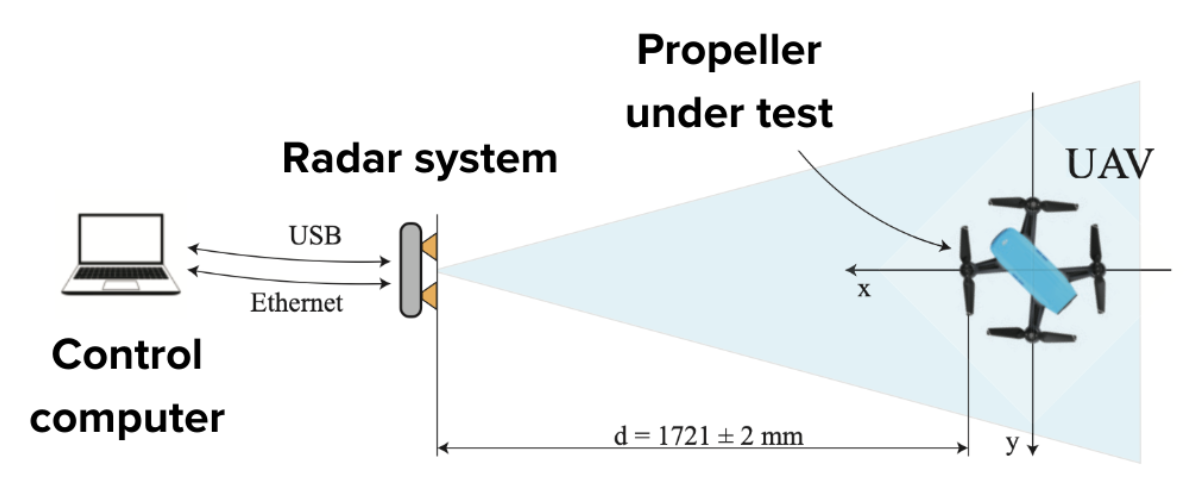
Figure 1: The team used this experimental setup for radar acquisition.
To perform this research, associate professor Susanna Spinsante, post-doctoral researcher Gianluca Ciattaglia, and their colleagues utilized Moku:Go, an FPGA-based test device offering 15+ software-defined instruments in a single piece of hardware. These instruments range from quintessential engineering tools like an Oscilloscope to advanced instruments like a Laser Lock Box. The wide array of easy-to-use instruments enables researchers to achieve more, faster, in settings ranging from classroom labs to industry R&D facilities.
The challenge
The rotational speed of propellers on drones and other UAVs is a difficult quantity to extract. This is because drone blades have an extremely small radar cross section, making them nearly impossible to detect. In order to use radar to effectively identify these small UAVs, the research team at UNIVPM considered multiple measurement methods. First, they considered measuring the velocity on the range-Doppler map to extract speed and length of the blades. However, they found that this method is not suitable for high-speed UAVs, since the requested pulse repetition frequency of the transmitted radar pulses should be very high. Next, the team considered measuring the micro-Doppler effect of the propellers, but faced the same limitations as measuring velocity. Additionally, gathering the range of instruments and equipment required to make these measurements is a costly and time-consuming endeavor.
To make progress, the team decided to turn to another method: measuring the side effect of the rotation, rather than measuring the rotation itself. By measuring the vibrations of the drone chassis introduced by propeller rotation, the team could attempt to circumvent the issues normally associated with UAV radar measurements.
The solution
With flexible, integrated instruments, Moku:Go provided an intuitive and effective solution to make UAV detection measurements faster and easier.
“Flexibility is one of the most relevant features of this platform and device,” Susanna said.
To perform the vibration analysis, the team utilized the following materials:
- RADAR system and control PC, 1721 mm from the BLDC motor of the UAV propeller
- ADXL accelerometer to monitor the propeller
- 10 MHz DAQ to measure triaxial acceleration voltage values
- DC power supply and ESC current driver
- Moku:Go M2 with embedded power supplies to control the rotational speed of the propeller and power the accelerometer
- Moku:Go Waveform Generator to provide a pulse-width modulation (PWM) control signal to the motor
- Two types of propellers: a 3-blade, 65-mm long propellor and a 2-blade, 130-mm long propeller
The team acquired signals from the accelerometer and radar sensor simultaneously to compare results. To do so, they sent a PWM signal from Moku:Go, with on-time set from 1.1 to 1.6 ms by a step of 0.1 ms. The team found that having the ability to control how they delivered their control signals to the motor was indispensable.
“We are using Moku devices quite often — they are powerful,” Susanna said. “We can easily set up different configurations and measurements with the same device, which is very useful, for example, when synchronizing the inputs and outputs.”
The researchers then performed a fast Fourier transform (FFT) on the collected data to determine the revolutions per minute (RPM) value of the propeller. To extract the vibrational information, they first analyzed the beat signals. Then, they organized their detected data in a cube, placing samples of a single chirp along an axis called Fast-Time. Next, they placed samples of different chirps along a Slow-Time axis. Finally, the placed samples from different receivers along the spatial sampling axis. The team then performed a bidimensional FFT of the Fast-Time, spatial sampling plane to produce Figure 2.
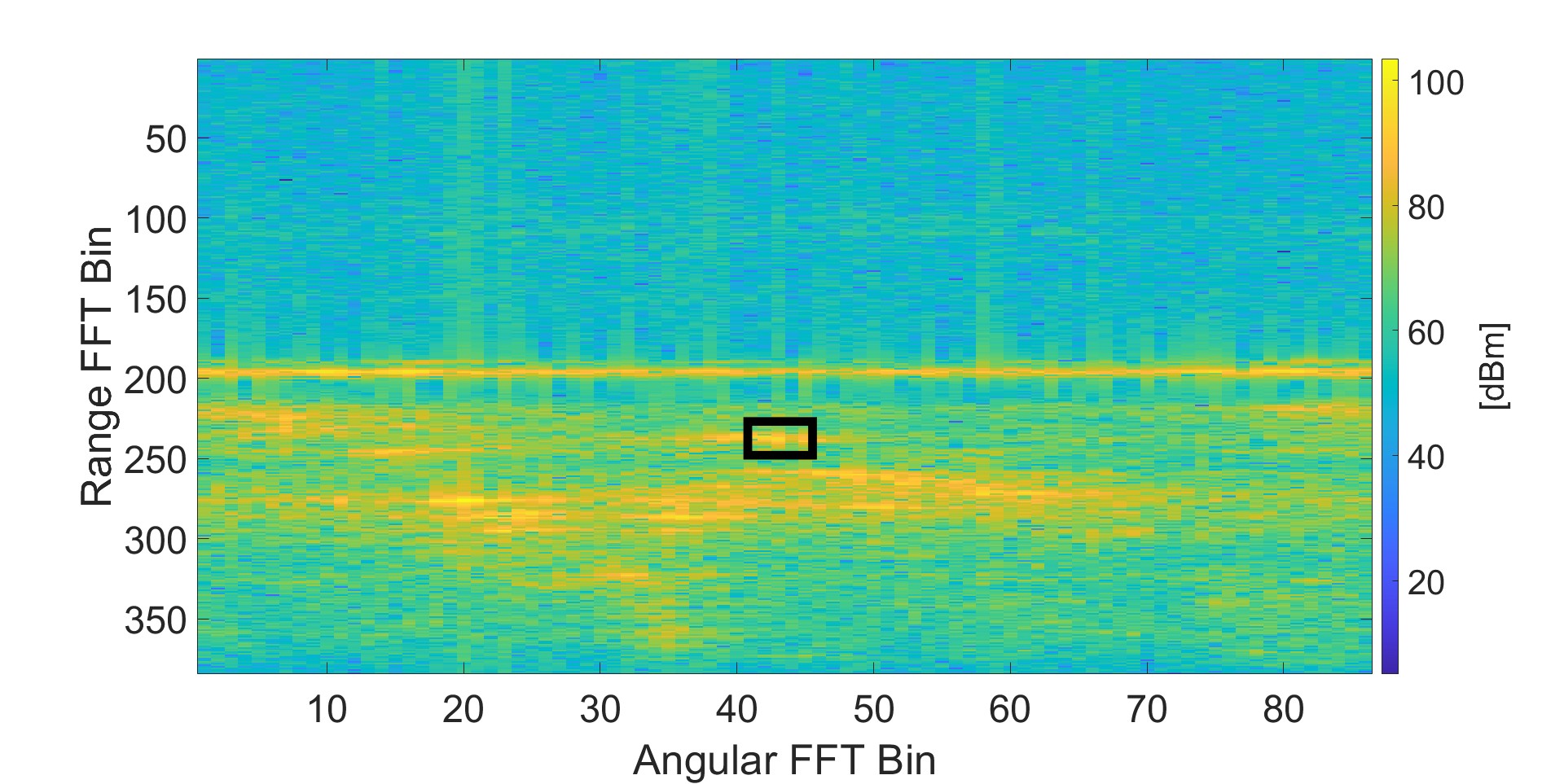
Figure 2: A sample detection map with FFT bins. The bin with the red frame identifies the position of the target.[1]
From this target position, the team could easily extract the phase of the signal and spatially filter out vibrations from undesired targets. Using this phase information, they can determine vibration displacement and even convert to meters to determine distance. For additional validation of the rotational speed, the team measured with a laser tachometer DT2234C+ and extracted the vibrational signal spectrum seen in Figure 3.
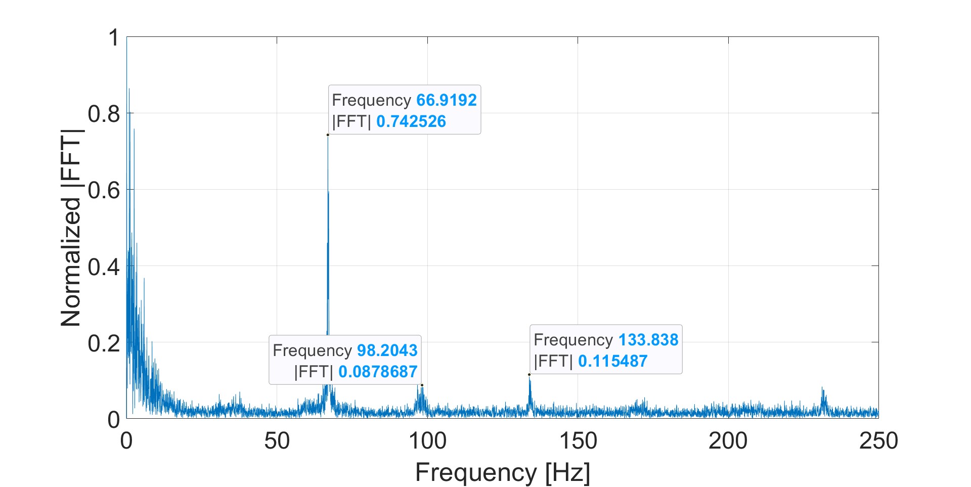
Figure 3: The vibrational signal spectrum of the two-blade propeller extracted by the radar sensor with a PWM duty cycle of 75%.[1]
The result
By integrating Moku:Go into their experiment, Susanna and Gianluca significantly streamlined their testing with robust, repeatable results while also seeing unexpected benefits.
“An interesting feature of Moku is the Wi-Fi connection,” Gianluca said. “I can start a measurement far away from my setup — other instruments don’t have this feature. Working with propellers, it’s preferable to stay away from the setup for safety reasons.”
After completing the experiment, the team saw a match between the rotation speed of the propeller extracted from the acceleration signals outfits motor, the rotation speed measured with a tachometer, and the rotation speed extracted from the measured vibrations. This verification unlocks more reliable methods to detect drones and other UAVs for critical defense applications. Table I displays the results for the three-blade propeller, while Table II shows the results for the two-blade propeller, both with low levels of error between measurement methods.
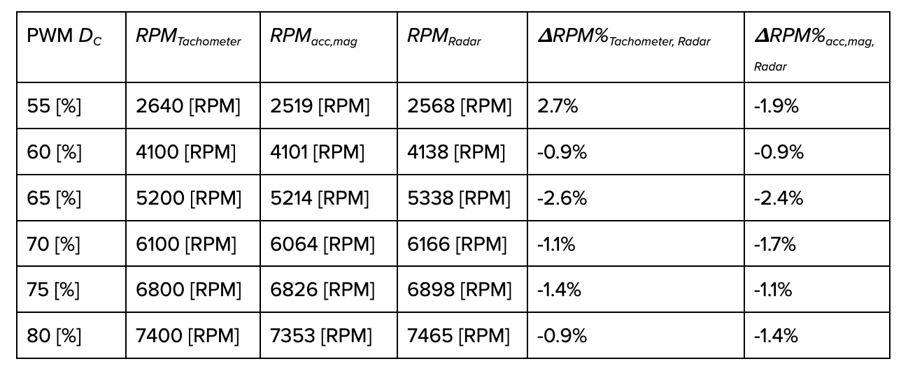
Table I: The results from the three-blade propeller with RPM values computed from the extracted frequency of acceleration and radar signals are rounded down to the integer; reproduced from paper [1].
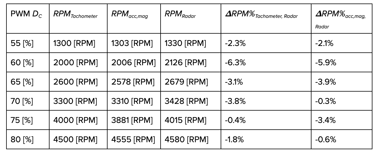
Table II: The results from the two-blade propeller with RPM values computed from the extracted frequency of acceleration and radar signals are rounded down to the integer; reproduced from paper [1].
Conclusion
Following the success of their experiment, Susanna and Gianluca have plans to expand their research and use of Moku:Go. In the future, they plan to use a calibrated accelerometer as a reference value for vibrational displacement, as well as aim to determine which other physical phenomena can be exploited to measure UAV propeller rotational speed without direct access to the drone.
Aside from this application, Susanna uses Moku:Go to introduce undergraduate students to the principles of electronic measurement. She also uses it to teach graduate-level courses focused on sensors and transducers. Susanna, her collaborators, and her students all use Moku:Go to prepare labs, reports, and presentations.
“A very useful feature is the ability to export traces, waveforms, and data in a MATLAB format,” Susanna said. “This is ready for the students, or for us, if we need to prepare drafts for our papers.”
Gianluca also uses Moku:Go across his experiments, pointing to the triggered data logging capabilities and storage benefits.
“It’s useful when you’re performing a lot of measurements,” he said. “You can store all the data on the Moku device, then download after the experimental part of your work.”
Questions?
Get answers to FAQs in our Knowledge Base
If you have a question about a device feature or instrument function, check out our extensive Knowledge Base to find the answers you’re looking for. You can also quickly see popular articles and refine your search by product or topic.
Join our User Forum to stay connected
Want to request a new feature? Have a support tip to share? From use case examples to new feature announcements and more, the User Forum is your one-stop shop for product updates, as well as connection to Liquid Instruments and our global user community.
Footnotes
[1] G. Ciattaglia, G. Iadarola, L. Senigagliesi, S. Spinsante, and E. Gambi, “UAV Propeller Rotational Speed Measurement through FMCW radars,” Remote Sensing, vol. 15, no. 1, Jan. 2023. doi:10.3390/rs15010270


