


Application notes
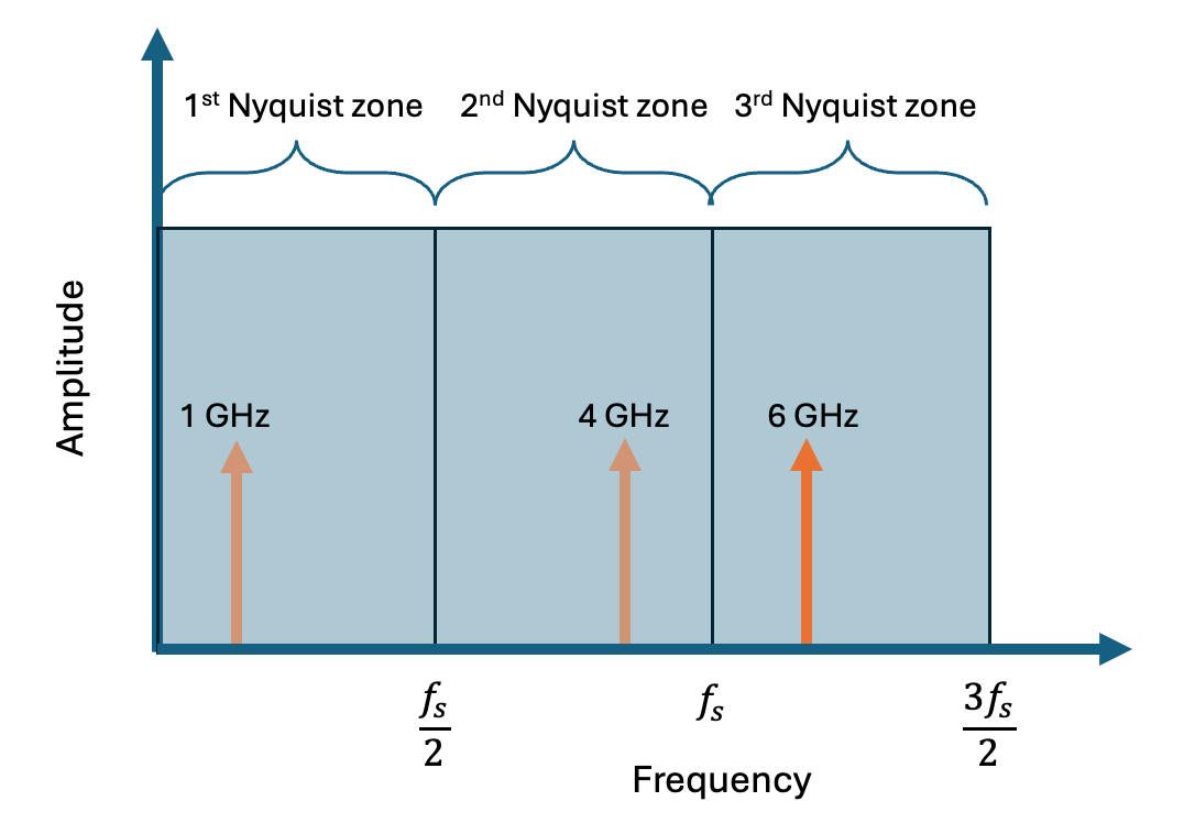
In this application note, we discuss how to acquire and analyze signals above the Nyquist frequency on Moku:Delta, making use of the full analog frontend of the device. We review the concepts of the Nyquist-Shannon sampling theorem and the constraints it places on digital sampling. We explain the advantages of this method and important considerations for making use of it. We illustrate several examples using the Moku:Delta 6 GHz mode to make measurements above the first Nyquist zone.
Featuring: Moku:Delta, Spectrum Analyzer
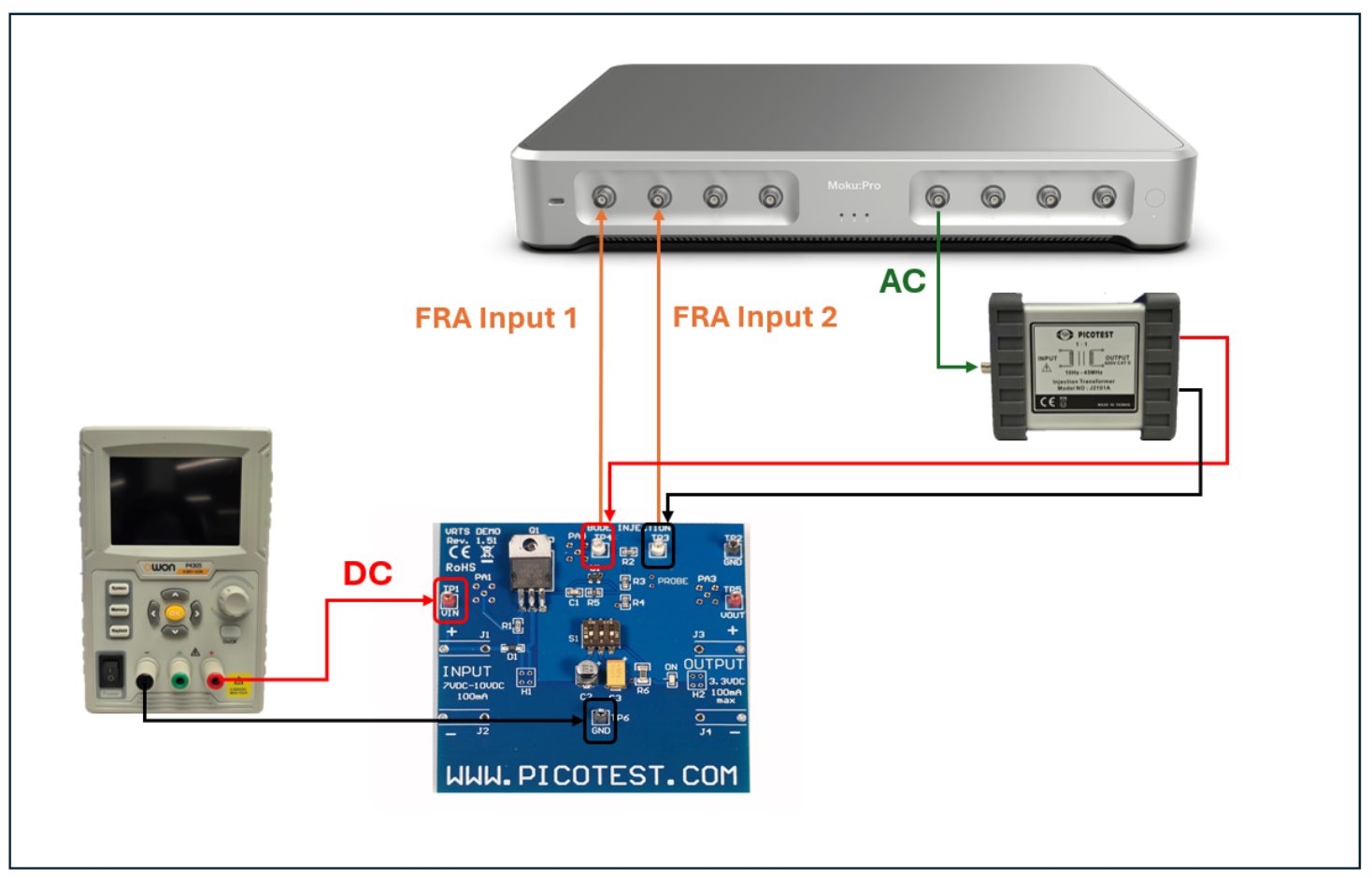
In this application note, we demonstrate how to perform both traditional (invasive) and non-invasive stability measurements (NISM) on a voltage regulator (VRTS 1.5) using the Frequency Response Analyzer on Moku:Pro . By comparing the two methods, we show that the NISM technique provides phase margin estimates that closely match those from traditional loop - breaking measurements, while eliminating the need to physically interrupt the circuit . These results confirm that NISM is a reliable and efficient tool for assessing control loop stability, offering engineers a faster and more practical alternative to conventional techniques.
Featuring: Moku:Pro, Frequency Response Analyzer
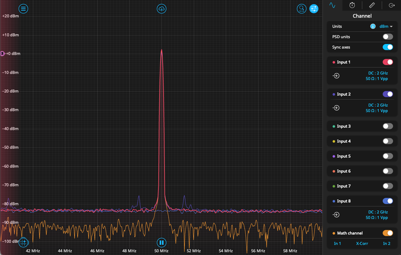
Cross-correlation a useful technique in signal processing, essentially comparing the similarity of two signals. We discuss its use in signal processing applications. Finally, we present the concept of cross-power spectral density, which is the equivalent of cross correlation in the frequency domain, using the Moku Oscilloscope and Spectrum Analyzer to illustrate several examples.
Featuring: Spectrum Analyzer, Moku:Delta
A concise guide to configuring direct sample streaming between two Moku:Delta devices using the Gigabit Streamer, including instrument placement, SFP connections, routing, and essential network parameters for reliable real-time operation.
Featuring: Moku:Delta, Gigabit Streamer
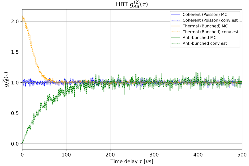
In this application note, we give an overview of the second-order correlation function and its physical meaning. We then discuss how to set up and collect the requisite data using the Moku Time & Frequency Analyzer, as well as use the built-in correlation calculator. Finally, we demonstrate two different methods for calculating the function and show that they agree well with each other.
Featuring: Moku:Pro, Time & Frequency Analyzer
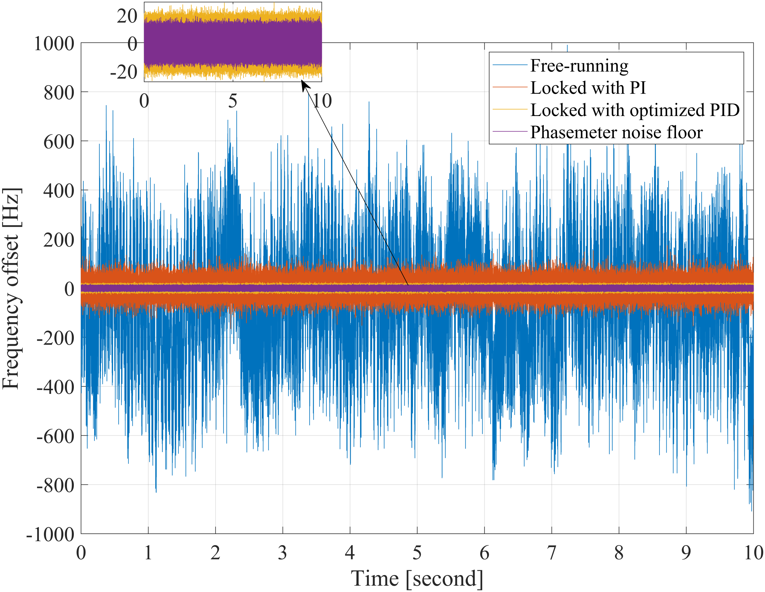
In this application note, a voltage-controlled oscillator (VCO) is stabilized using the Moku:Pro in Multi-Instrument Mode, integrating a Lock-in Amplifier for error detection and feedback control with a Frequency Response Analyzer for measuring the transfer function. The system’s open loop transfer function (OLTF) is modeled, simulated, and validated against experimental measurements.
Featuring: Moku:Pro, Frequency Response Analyzer, Lock-in Amplifier
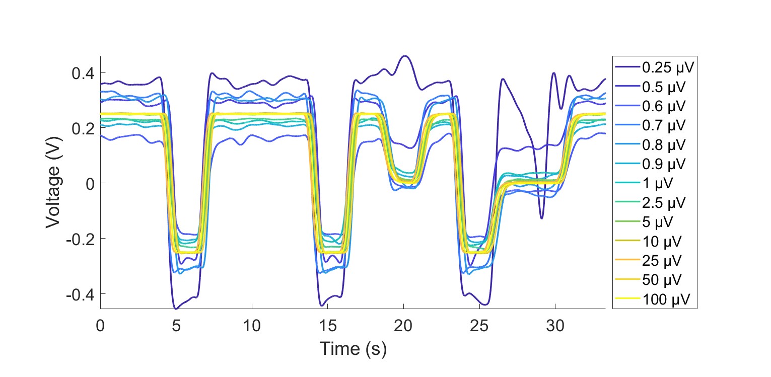
In this application note, we demonstrate how to phase-modulate and externally attenuate a high-frequency tone to achieve peak-to-peak signal amplitudes in the microvolt and sub-microvolt range.
Featuring: Moku:Pro, Lock-in Amplifier
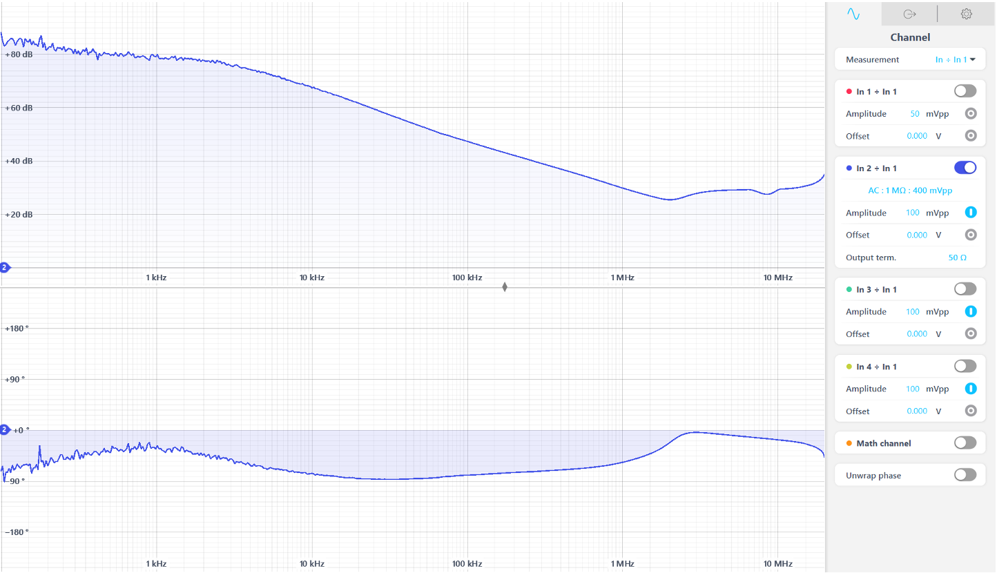
In this application note, the Frequency Response Analyzer is used to inject a perturbation signal onto the DC input of a voltage regulator, and to measure the transfer function of the input ripple to the output ripple of the regulator.
Featuring: Moku:Pro, Frequency Response Analyzer
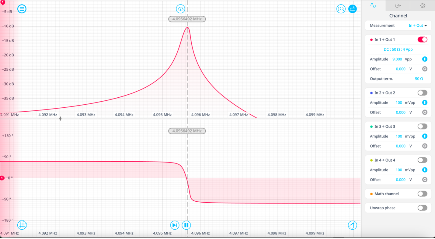
Learn how the DFRT method works when tracking the resonant peak of a crystal to test the real-world capability.
Featuring: Moku:Pro, Frequency Response Analyzer, Waveform Generator, Phasemeter, Lock-in Amplifier